MTS Series 505G2 SilentFlo Hydraulic Power Unit Model 505G2-30 User Manual
Page 29
505.20/.30 HPU Connections
Model 505G2.20 - 505G2.30 SilentFlo™ HPU
Installation
29
The first time a pump motor is started after electrical service is connected to
the HPU, it is possible for the pump motor to rotate in the wrong direction.
A pump motor rotating in the wrong direction at high pressure for longer
than 10 seconds can cause severe damage to your HPU.
If the output pressure does not increase within 10 seconds after High is selected,
stop the unit.
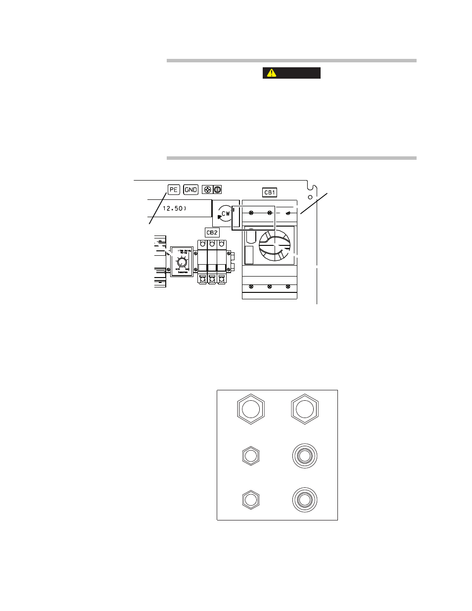
2. Connect the grounding wire to the lug labeled PE GND (protective earth
ground).
Connecting the
hydraulic lines
The figure shows the hydraulic adapter ports to the HPU.
Note
Each hydraulic connection requires an O-ring face seal.
CAUTION
L1 L2 L3
PE GND (Protective
Earth Ground) Lug
Electrical Power Feed
Lugs (shown labeled for
clockwise phase
orientation)
Ensure that lugs are
secure. They should be
checked periodically.
See the Maintenance
section.
Return
-16 (1 in)
Drain
-8 (1/2 in(
Water In
1 in NPT
Pressure
-16 (1 in)
Drain
-6 (3/8 in)
Water Out
1 in NPT