20/.30 hpu hydraulic schematic, 20/.30 hpu hydraulic schematic 18 – MTS Series 505 SilentFlo Hydraulic Power Unit Model 505-30 User Manual
Page 18
Model 505.20 - 505.30 SilentFlo™ HPU
18
505.20/.30 HPU Hydraulic Schematic
Introduction
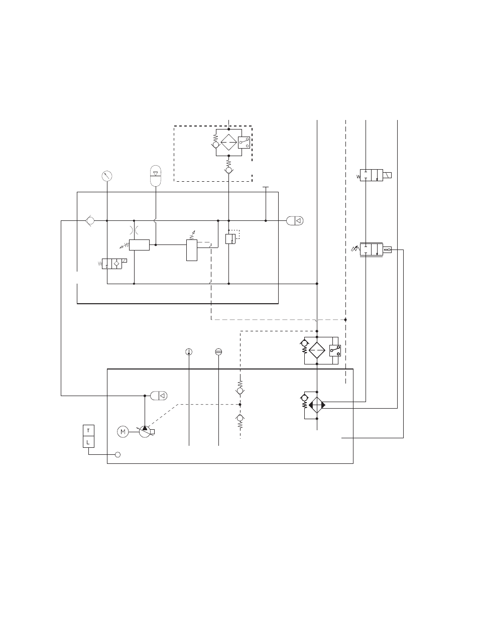
505.20/.30 HPU Hydraulic Schematic
The hydraulic schematic shows the functional layout of the Series 505 Hydraulic
Power Unit.
Water
Shutoff
Valve
Water
Regulator
Valve
Heat
Exchanger
Sight
Gage
Temperature
Gage
Pump Drain
Check Valve
0.014 MPa (2.0 psi)
Pump Drain
Check Valve
0.034 MPa
(5.0 psi)
3 Micron
Filter
Reservoir
Pump
Motor
Surge
Suppressor
Temperature and
Low Level
Sensor
Control Manifold
Pressure
Gage
Oil Sample
Port
Accumulator
(optional)
Pressure Filter
(optional)
Auto-cooling
Valve
(adjustable)
Check
Valve
High Pressure
Solenoid Valve
Auto-cooling
Valve
(factory set)
Accumulator
P
R
D
W
W
0.063 inch Orifice
0.007 MPa (1.0 psi)
Pressure
Relief Valve
(factory set at
22.4 MPa
(3250 psi)
This manual is related to the following products: