20/.30 hpu component identification, 20/.30 hpu component identification 14 – MTS Series 505 SilentFlo Hydraulic Power Unit Model 505-30 User Manual
Page 14
Model 505.20 - 505.30 SilentFlo™ HPU
14
505.20/.30 HPU Component Identification
Introduction
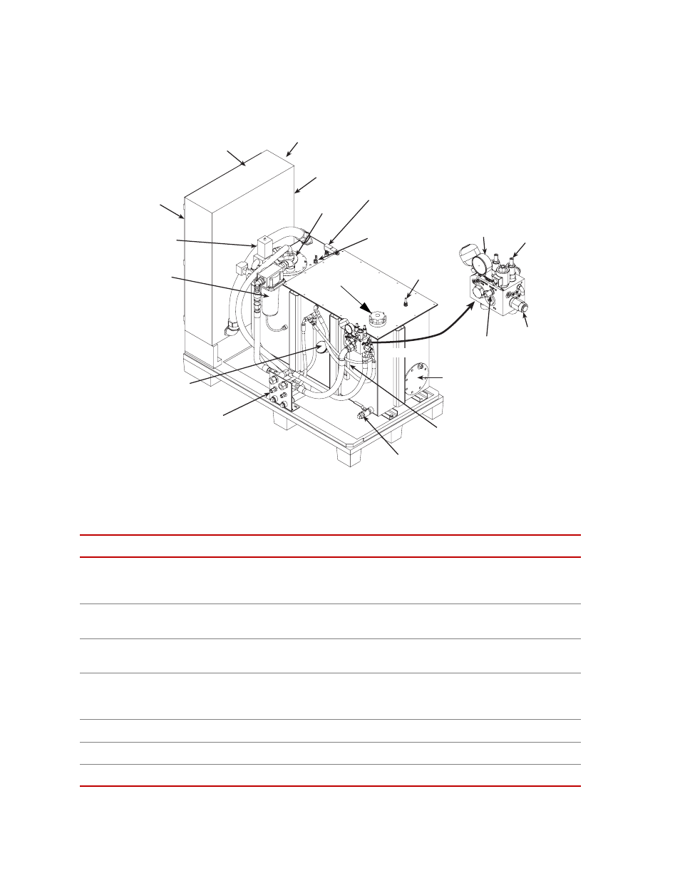
505.20/.30 HPU Component Identification
Component Locations
Component Descriptions
Component
Description
Auto-Cooling Valve
Keeps the hydraulic fluid clean and cool by circulating the fluid through the return
filter and the heat exchanger while the HPU is in high pressure mode and the fluid
demand by the external circuit is very low.
Commoning Port
Used in multiple HPU operation. Ensures that commoned reservoir levels are
balanced.
Control Panel
Controls the operation of the power unit and indicates the current status of several
detectors.
Electrical Enclosure
Houses the HPU’s wye-delta starter and control components. The main power lines
enter the unit at the top. The power disconnect switch removes electrical power
whenever the enclosure’s door is opened.
Filler Cap
Vents the hydraulic fluid reservoir. This is where you add hydraulic fluid.
Filter
Filters particles out of the hydraulic fluid as it is returned to the HPU.
Fluid Drain
Drains the hydraulic fluid from the reservoir.
Nameplate
Electrical
Enclosure
Control Panel
(other side of box)
Power Disconnect
Switch (other side
of box)
Heat
Exchanger
Low Level/
Overtemperature
Sensor
Output
Pressure
Gage
Pressure
Relief
Valve
Fluid
Sample
Port
Commoning
Port
Sight Gage
(on reservoir)
Fluid Drain
Hydraulic and
Water Ports
Temperature
Gage
Filter
Water Flow
Regulator
Surge Supressor
Charge Valve
Filler Cap
Output
Pressure
Control
Auto-
Cooling
Valve
Control
Manifold