Temperature setpoints, Temperature setpoints 29 – MTS Model 409.83 Temperature Controller User Manual
Page 29
Temperature Setpoints
Model 409.83 Temperature Controller
Operation
29
Temperature Setpoints
Normal operation of the temperature controller requires the desired temperature
setpoints to be entered into each control module. After the setpoints have been
entered, the heater elements can be enabled.
To enter the temperature setpoints:
1. From the Home display, press the up or down arrow (to increase or decrease
the current value).
3
SP2
Setpoint 2
When lit, this indicates that setpoint 2 has been selected.
4
REM
Remote
Setpoint
When lit, this indicates that the PDSIO remote setpoint
input has been selected.
5
MAN
Manual
Mode
When lit, it indicates that manual mode has been
selected.
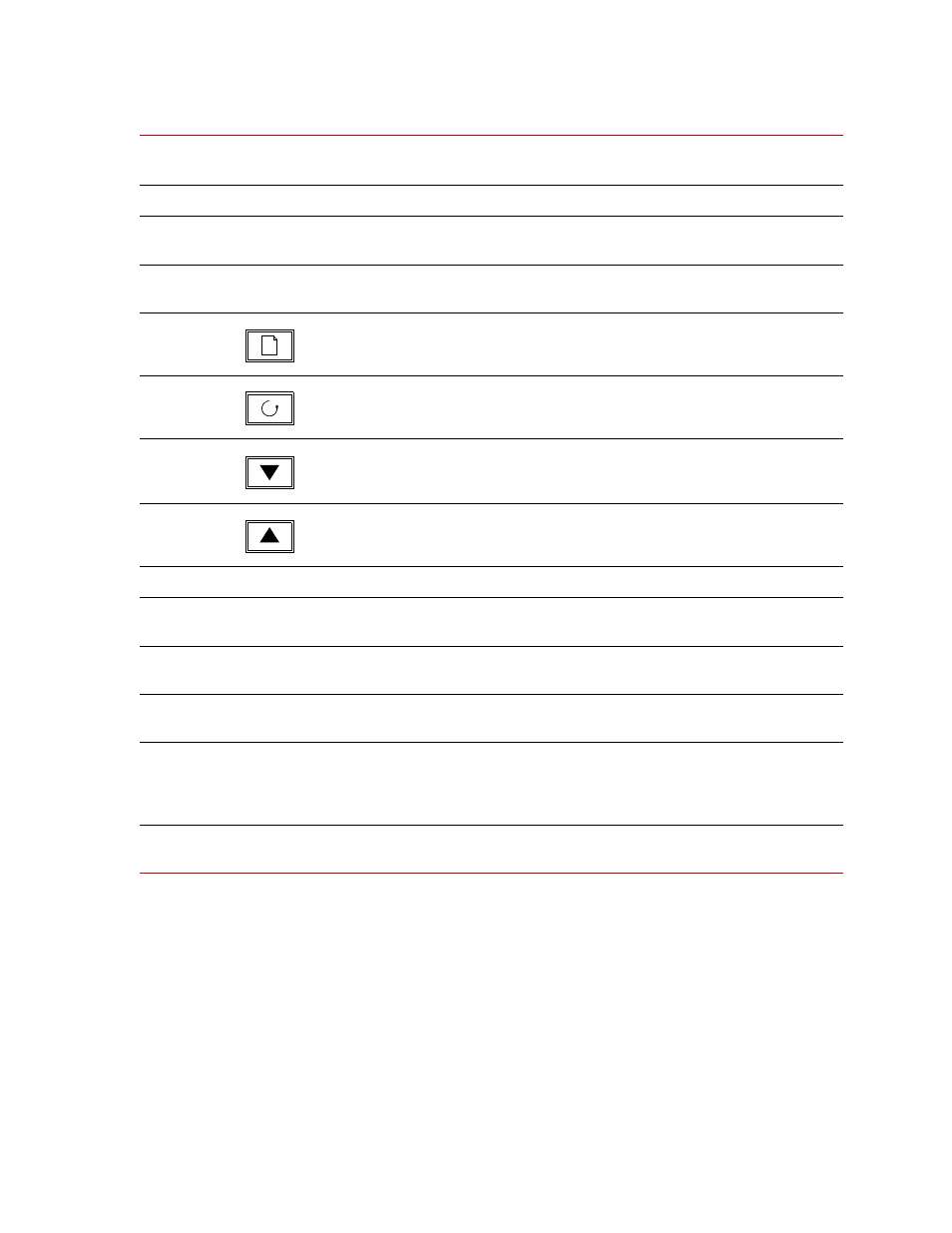
6
Page Button
Press to select a new list of parameters.
7
Scroll Button
Press to select a new parameter in a list.
8
Down Button
Press to decrease a value in the lower readout.
To speed up the rate of change, press and hold the button.
9
Up Button
Press to increase a value in the lower readout.
To speed up the rate of change, press and hold the button.
10
RUN
Run Indicator
When lit, it indicates that setpoint rate limit is active.
11
LCD Display
Readout
Displays temperature controller data (temp readout,
setpoint, parameter value, and so forth.)
12
Switch/Indicator
(red)
Disable
Disables the heating elements of the high-temperature
furnace.
13
Switch/Indicator
(green)
Enable
Enables the heating elements of the high-temperature
furnace.
14
Indicator (yellow)
Alarm
Functions in conjunction with the alarm indicators of
each temperature controller. When the interlock is
broken, the Alarm indicator lights, and power to the
elements is cut off.
Not
Shown
Power Switch
I / O
Chassis power switch (on back panel). On is labeled I,
Off is labeled O.
Controls and Indicators (Continued)
C
ALLOUT
C
ONTROL
OR
I
NDICATOR
N
AME
D
ESCRIPTION