MTS Series 249G2 Swivels User Manual
Page 23
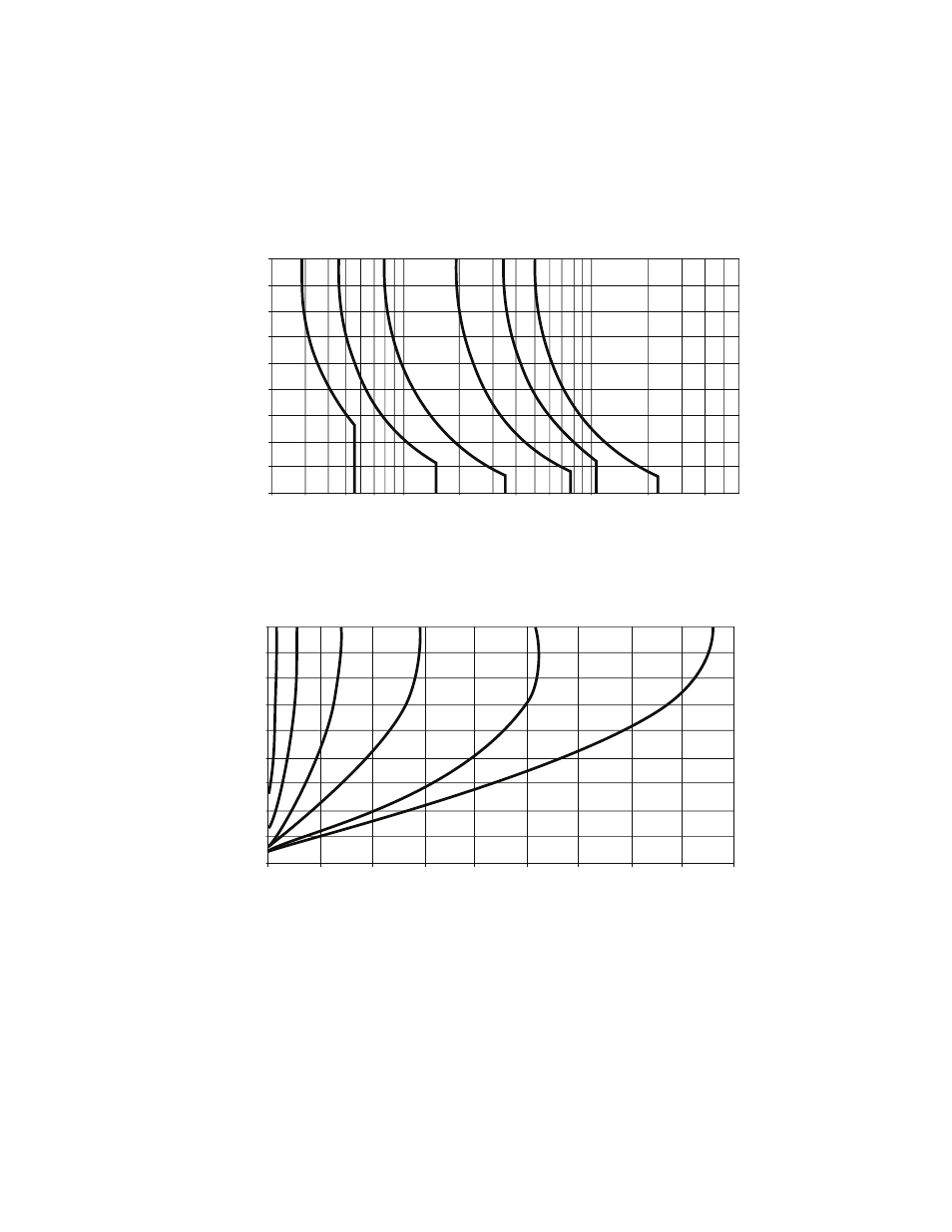
Mounting for Angularly Applied Loads
Series 249G2 Swivels
Installation
23
Different system configurations require the use of different types of retaining
stops. In all cases, the retaining stops must withstand a shear force equal to or
greater than the forces specified in the following illustrations.
Systems that require the swivels to react angularly to applied tensile and
compressive loads should also take into account the possibility of backlash
between the retaining stops and the swivel jaw. The retaining stops should be
mounted in a manner that will eliminate or minimize this backlash.
F (force to produce slippage)
90
80
70
60
50
40
30
20
10
0
3000
13.344
5000
22.241
7000
31.137
10,000
44.482
20,000
88.964
40,000
177.928
60,000
266.892
100,000
444.820
200,000
889.640
β
(degrees of rotation from the vertical
)
lbf
kN
400,000
1,779.28
2000
8.896
249.xx.M25 249.xx.M70
249.xx.M160
249.xx.M340
249.xx.M500249.xx.M1000
90
80
70
60
50
40
30
20
10
0
20,000
88.964
lbf
kN
0
40,000
177.928
60,000
266.892
80,000
355.851
100,000
444.820
120,000
533.777
140,000
622.740
160,000
711.702
180,000
800.665
β
(degrees of rotation from the vertical)
Shear strength of retaining stops
249.xx.M25
249.xx.M70 249.xx.M160
249.xx.M340
249.xx.M500
249.xx.M1000