Switch 1, Switch 2 – MMF POS Standard RS-232 Connection Interface Kit User Manual
Page 4
531-8661-00 MMF Multi-Serial Interface Page 3 of 12
Switch 1
When the indicated Switch is ON, all other specified Switches in the same column must be OFF
JP1
when SW1-pos 8 is in the ON position, jumper JP1 must be placed in the SIG position (jumper across pins
1 and 2 of JP1).
JP1
must be placed on the PWR position (jumper across pins 3 and 2 of JP1) when receiving power via pin 9
from a PC powered serial port.
Switch 2
SW2 Functions only apply when the controller is set to "Smart Mode" (SW3-1 = ON)
P
O
S
SW2
FUNCTION
1
ASCII Character Bit 0 (LSB)
2
ASCII Character Bit 1
3
ASCII Character Bit 2
4
ASCII Character Bit 3
5
ASCII Character Bit 4
6
ASCII Character Bit 5
7
ASCII Character Bit 6
8
ASCII Character Bit 7 (MSB)
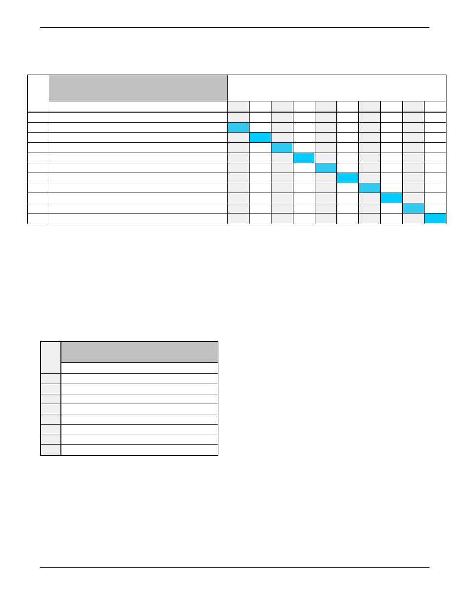
POS
SW1
SW1 CONFIGURATION CONSTRAINTS
FUNCTION (when ON)
1
2
3
4
5
6
7
8
9
10
1
Loop DTR (pin 4) to DCD (pin 1)
ON
OFF
2
Loop DTR (pin 4) to DSR (pin 6)
OFF
ON
OFF
3
Loop CTS (pin 8) to RTS (pin 7)
ON
OFF OFF
4
Receive Drawer-Open data input on TXD (pin 3)
ON
OFF OFF
OFF
5
Receive Drawer-Open data input on RXD (pin 2)
OFF
ON
OFF
6
Receive Drawer-Open data input on CTS (pin 8)
OFF OFF OFF
ON
OFF
7
Send Drawer-Status output on CTS (pin 8)
OFF
OFF
ON
OFF OFF
8
Send Drawer-Status output on RI (pin 9) -see JP1
OFF
ON
OFF
9
Send Drawer-Status output on DSR (pin 6)
OFF
OFF OFF
ON
10
Re-Transmit Drawer-Open data signal on TXD (pin 3)
OFF
ON