MMF POS Standard RS-232 Connection Interface Kit User Manual
Page 3
531-8661-00 MMF Multi-Serial Interface Page 2 of 12
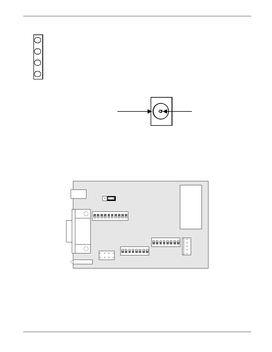
LED Signal Status Panel
LED #4 (top-red) DTR / DSR / DCD Status; LED is ON when there is activity on any of these lines
LED #3 (red) RTS / CTS Status; LED is ON when there is activity on any of these lines
LED #2 (red) Drawer Status. Open / Close inner drawer indicator.
LED #1 (green) Power good when ON solid / Data received when blinking
Supply Voltage
Power connector
+12 VDC
γ 5% 0.8 A.
Plug required for Power connector:
OD: 5.5mm
γ
0.1mm
-
+
ID: 2.1 mm
γ
0.1mm
Length: 8.75 mm
γ
0.5mm
DIP Switch settings
To modify the cash drawer settings locate the serial interface module plate on the back of the cash drawer as
shown on Figure 1, remove the two side screws to access the serial PC board and locate the three banks of DIP
switches SW1, SW2 and SW3 as shown in Figure 2.
SW2
SW3
SW1
P2
JP1
SIG
PWR
SW3
SW2
SW1
P
1
J1
P3
Figure 2
3 2 1
ON
OFF
ON
OFF