MMF POS 12V PoweredUSB Interface Kit User Manual
Powered, Usb interface board, Components
PoweredUSB Interface Board
Instruction manual / User Guide
Approved Date of Revision 5/1/2010 Doc. PoweredUSB
Instruction Manual
Powered
USB Interface Board
COMPONENTS
2261998PWRUSB-XX – PoweredUSB
Interface KIT
Part# 641-25CJ-00- PoweredUSB Cable
INSTALLATION
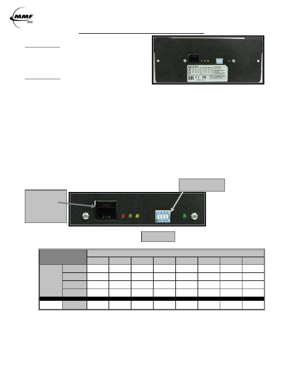
Select Cash Drawer Number
The MMF POS USB Interface Board is factory defaulted to recognize the first cash
drawer to be installed as drawer number seven (7), see Figure 1.0 Dip-Switch Position
(Default Setting). If user decides to assign another drawer number, please follow the
pin configuration illustrated in SWITCH SETTINGS Table 1.0 or label attached to the
interface for correct pin orientation.
Connect the 12V PoweredUSB Rated Cable to the host (12VDC / .8 Amp)
Plug the 2x4 Molex Latch-n-Lock connector end to the USB Port of the interface and the
12V Connector (Color:Teal) end to the corresponding 12V jack PoweredUSB port of the
Host Computer or PoweredUSB Hub.
Test Functionality of Interface
Follow the steps detailed below for ‘USB Test Utility Installation’.
Install OPOS Drivers (If Required)
Follow the steps detailed below for ‘MMF OPOS Drivers Installation’.
NOTE: Do not assign two (2) USB interface cash drawers within the same system with the same cash drawer number.
FIGURE 1.0
TABLE 1.0
SWITCH SETTINGS
DRAWER
0
1
2
3
4
5
6
7
D
IP
-S
W
ITC
H
SW1
ON
OFF
ON
OFF
ON
OFF
ON
OFF
SW2
ON
ON
OFF
OFF
ON
ON
OFF
OFF
SW3
ON
ON
ON
ON
OFF
OFF
OFF
OFF
SW4
OFF
OFF
OFF
OFF
OFF
OFF
OFF
OFF
Reset
Statistics
SW4
ON
ON
ON
ON
ON
ON
ON
ON
NOTE: OFF is when pins are facing down (
↓). ON is when pins are facing up (↑).
NOTE: ONLY place SW4 on the ON Position if you will like to reset the statistics stored and reported though
the OPOS Drivers.
DIP-SWITCH POSITION
Default Setting: Drawer 7
USB Port
Port of Cash Drawer
Interface
Connect Type B
Connector of USB
cable Here
1 2 3
4
LEDS