Mayline LT BASE User Manual
Page 2
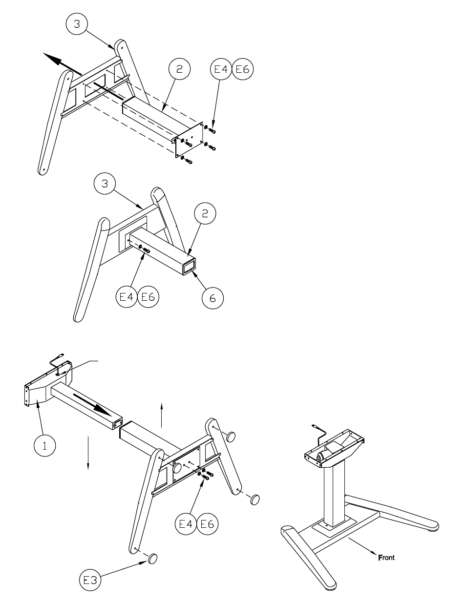
1. Insert Column Brace Assembly (2) through bottom of
Angled Base Assembly (3). Align the holes in the
column assembly plate with the holes in the Base.
2. Install four M8 x 16 mm Cap Screws (E6) and four
Lock Washers (E4). DO NOT TIGHTEN at this time
3. Install two M8 x 16mm Cap Screws (E6) and two
Lock Washers (E4) on either side of Column through
the top of the Base. Tighten all screws, top and bottom,
at this time.
Actuator cord access hole
toward back of unit
Front
Back
4. Slide Actuator Assembly (1) into assembled base.
Position the cord access hole toward the back of the
assembly.
5. Secure Actuator Assembly (1) to the bottom of the
Base (3) using two M8 x 16mm Cap Screws (E6) and
two Lock Washers (E4). Tighten Screws securely.
6. Install Glides (E3) into the Base.
7. Stand assembled unit upright.
(2)