Assembly instructions for mounting straightedge – Mayline Convert Rule to Above Board Attachmen User Manual
Page 3
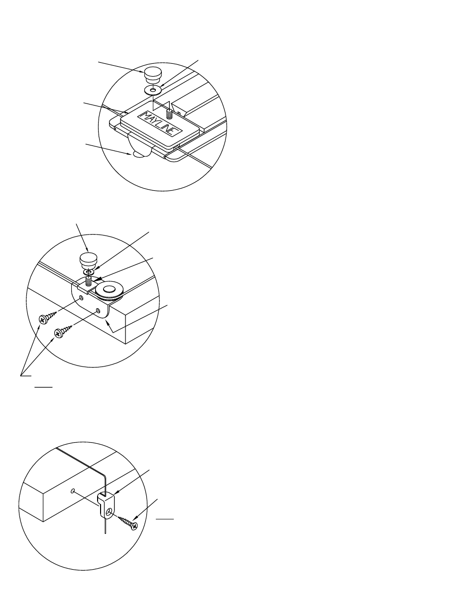
1. Place straightedge in position on Worksurface.
Install Knob (E10) and Washer (E6) on both ends
of straightedge. Do not tighten at this time. (See
Fig. #4)
2. IF STRAIGHTEDGE IS FULL LENGTH OF
WORKSURFACE AND NO SIDE MOTION IS
DESIRED: Insert Side Guides (E4) under pulley
housing cover as shown in Fig. #4. Guides may
be bent with fingers to fit Worksurface.
IF STRAIGHTEDGE IS NOT FULL LENGTH OR
SIDE GUIDES ARE NOT DESIRED: Side Guides
can be eliminated without affecting operation of
unit.
3. Position Corner Plates (E1) and (E2) so cable
runs parallel with Worksurface edge. (See Fig.
#5). Mark hole locations.
4. Drill 3/32" pilot holes at marked locations.
5. Secure Corner Plates using four #6 x 1/2
Screws (E7). (See Fig. #5)
6. Install cable Clamp (E12) onto Stud of Left
Corner Plate (E2). Be sure cable passes between
Clamp and Corner Plate. Turn Knob (E10) onto
Stud. (See Fig. #5 for correct installation). See
Fig. #7 for Spring position. Tighten Knob (E10)
when spring is centered.
7. Position the Stedge Stop (E3) on the front
edge so the cable is parallel with the Worksurface
sides. Mark holes on the Worksurface edge.
(See Fig. #6) Repeat this step for both sides.
8. Drill 3/32" pilot holes at marked locations.
9. Insert cable through Stedge Stop and attach to
the Worksurface using Screws (E9).
#6 x 1" Screw (E9)
NOTE:
Pre-drilling 3/32" pilot holes is
recommended for these screws.
Stedge Stop (E3)
Left Corner
Plate (E2)
Cable Clamp (E12)
#6 x 1/2" Screws (E7)
NOTE:
Pre-drilling 3/32" pilot holes is
recommended for these screws.
Fig. #6
Fig. #5
Pulley Housing
Cover
Knob (E10)
Side Guide (E4)
Washer (E6)
Fig. #4
ASSEMBLY INSTRUCTIONS
for MOUNTING STRAIGHTEDGE
Knob (E10)
Washer (E6)
(3)