6 wiring, 1 operation with ecsxe power supply module, Operation with ecsxe power supply module – Lenze ECSxK series User Manual
Page 31: Electrical installation, Stop, Wiring operation with ecsxe power supply module, Show/hide bookmarks, Ecsxkxxx, Ecsxexxx, Ecsxaxxx
Electrical installation
Wiring
Operation with ECSxE power supply module
5
31
EDBCSXKXXX EN 1.0
5.6
Wiring
5.6.1
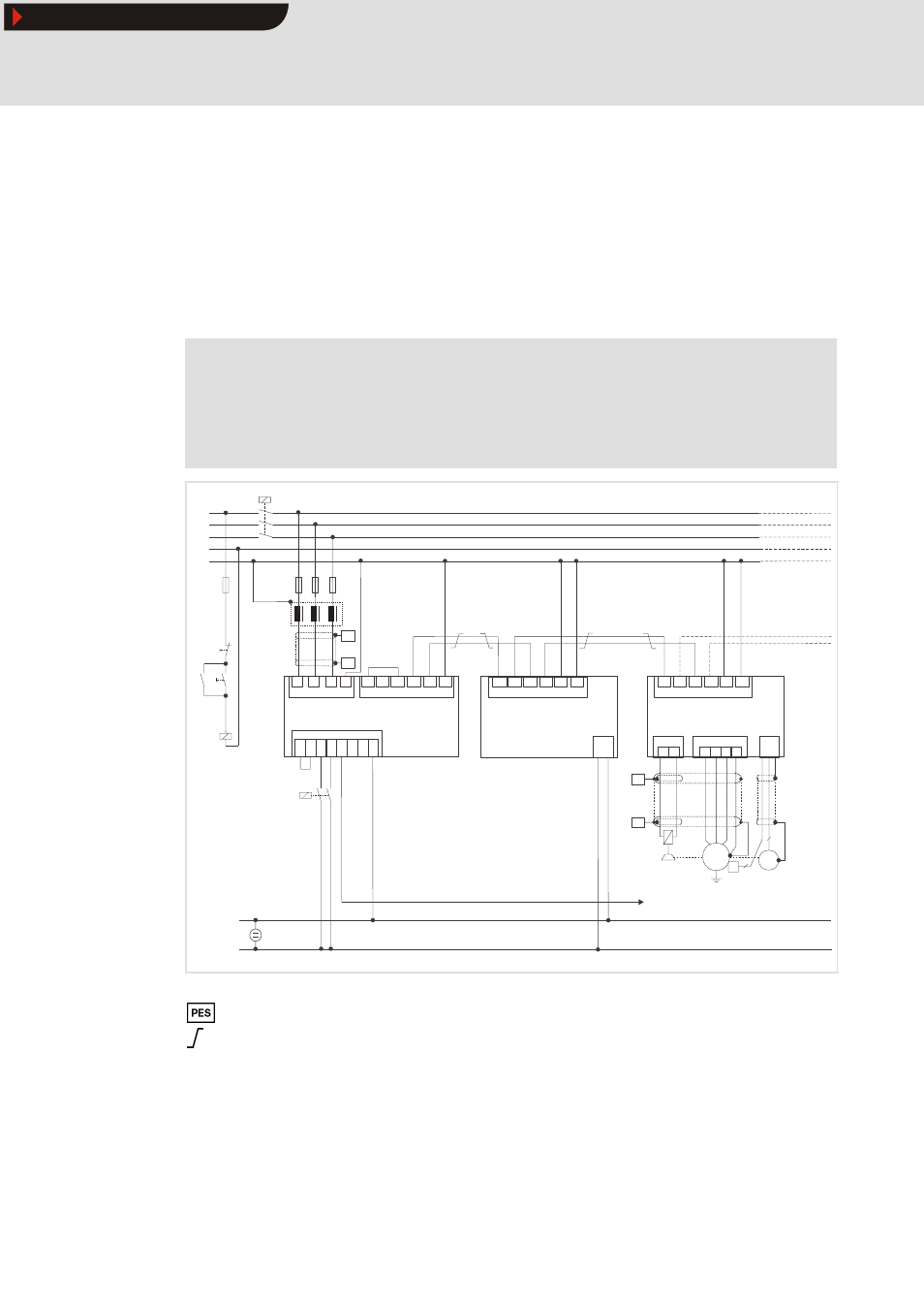
Operation with ECSxE power supply module
Install the capacitor module ECSxKxxx between the power supply module and the axis
module(s).
If the total cable length in the DC-bus connection is longer than 5 m, install the capacitor
module as close as possible to the axis module with the highest power.
Stop!
ƒ
Permanently bridge the charging current limitation (X26) of the capacitor
module (X26 = HIGH).
ƒ
Only release the controller (X6/SI1 = HIGH) if the power supply module
ECSxE displays ”Ready for operation” (X6/DO1 = HIGH).
L3
N
PE
L1
L2
F1...F3
Z1
F4
K1
ECSxKxxx
K1
K1
L1
L2
L3
ECSxExxx
PE
X21
+UG
+UG
+UG
+UG
+UG
-UG
-UG
-UG
-UG
-UG
PE
PE
PE
PE
PE
X22
X23
Off
On
+UG
BR1
X26
BR0
PES
PES
U
V W
ECSxAxxx
X23
PE
X24
B1 B2
X25
X7
M
3~
PE
PES
PES
R
J
*1
2
6
. . .
T1
T2
X6
DI1
DI2
DO1
D24
+24V
GND
GND
24 V DC
+
-
Ctrl. enable
K1
ECSXX004
Fig.5-2
Wiring of the capacitor module ECSxK with power supply module ECSxE
HF shield termination by large-surface PE connection
Twisted cables
* 1
System cable - feedback
Ctrl.
enable Terminal X6/SI1 of the connected axis modules (controller enable)
Show/Hide Bookmarks