Electrical installation – Lenze ECSEExxx User Manual
Page 83
Electrical installation
Power terminals
4
83
EDKCSEE040 DE/EN/FR 4.0
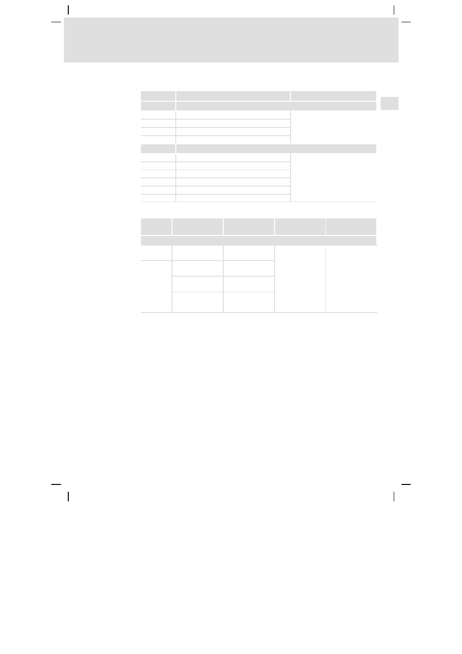
Assignment of the plug connectors
Terminal
Function
Electrical data
X21
Mains connection
X21/L1
Mains phase L1
Dependent on application and
type
0 ... 480 V
up to 31.3 A (
70)
X21/L2
Mains phase L2
X21/L3
Mains phase L3
X21/PE
Connection of PE conductor
X22
DC-bus voltage connection
X22/BR0
Internal brake resistor, connection 1
Dependent on application and
type
0 ... 770 V
up to 38.5 A (
70)
X22/BR1
External brake resistor, connection 1
X22/+UG
Internal/external brake resistor, connection 2
X22/+UG
DC-bus voltage supply, plus
X22/-UG
DC-bus voltage supply, minus
X22/PE
Connection of PE conductor
Cable cross-sections and screw-tightening torques
Cable type Wire end ferrule
Possible cable
cross-sections
Tightening torque
Stripping length
Terminal strips X21 and X22
Rigid
–
0.2 ... 10 mm
2
(AWG 24 ... 8)
1.2 ... 1.5 Nm
(10.6 ... 13.3 lb-in)
5 mm for screw
connection
10 mm for spring
connection
Flexible
Without wire end
ferrule
0.2 ... 10 mm
2
(AWG 24 ... 8)
With insulated wire
end ferrule
0.25 ... 6 mm
2
(AWG 22 ... 10)
With insulated
TWIN wire end
ferrule
0.25 ... 4 mm
2
(AWG 22 ... 12)
Shielded cables
The following factors decisively determine the effect of the shielded cables:
ƒ
Good shield connection
–
Ensure a contact surface as large as possible
ƒ
Low shield resistance
–
Only use shields with tin-plated or nickel-plated copper braids (shields
with steel braids cannot be used).
ƒ
High overlap rate of the braid
–
At least 70 ... 80 % with 90° overlap angle
The ECSZS000X0B shield mounting kit includes a wire clamp and shield sheet.