Scope of supply, Connections and interfaces, Status displays – Lenze ECSEExxx User Manual
Page 56
56
EDKCSEE040 DE/EN/FR 4.0
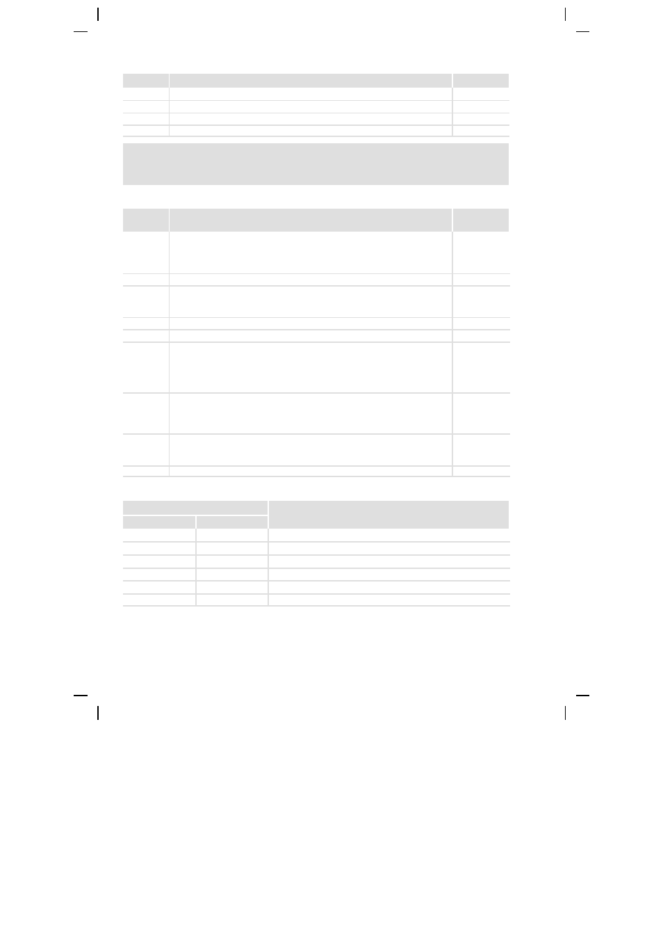
Scope of supply
Position
Description
Number
Power supply module ECSEExxx
1
Accessory kit with attachment material
1
Mounting instructions
1
Drilling jig
1
Note!
The ECSZE000X0B connector set must be ordered separately.
Connections and interfaces
Position
Description
Detailed
information
X22
Connections
External brake resistor
DC-bus voltage
PE
87
LEDs: Status and fault display
X1
Automation interface (AIF) for
Communication module
Operating module (XT keypad)
101
X2
PE connection AIF
X3
Not assigned
X4
CAN connection
System bus (CAN)
Interface for
– master control and other modules
– PC/HMI for parameterisation and diagnostics
102
X6
Connections
Low-voltage supply
Digital inputs and outputs
Thermostat contacts
100
S1
DIP switch
CAN node address (device address in the CAN network)
CAN baud rate
X21
Mains connection
84
Status displays
LED
Description
Red
Green
Off
On
Power supply module is enabled, no fault
Off
Blinking
Power supply module is inhibited (CINH), switch-on inhibit
Blinking, 1 Hz
Off
Fault / error (TRIP) / short-circuit braking error (KSB-TRIP) is active
Blinking, 3 Hz
Off
Message active
Blinking, 1 Hz
Blinking
Warning active with inhibited module
Blinking, 1 Hz
On
Warning active with enabled module