Drive registers 9 drive registers – Lenze ESVZAR0 RS-485 User Manual
Page 21
19
CMVMB401C
Drive Registers
9
Drive Registers
9.1
Data Internal vs. Display Representation
Register data passed across the Modbus communications link is always in INTERNAL units, although the drive itself
may show the information in some alternate DISPLAY units.
For register values with 1 or more decimal places, the actual value sent over the Modbus communications will be
the value times 10
DP
, where DP is the number of decimal places.
Example
An actual frequency of 34.3Hz would be sent over the network as 343 (34.3*10
1
).
If the drive is setup to display the actual frequency in RPM using P178 = 29.17, the actual speed would be displayed
on the drive as 1000 (RPM) but would still be sent over the Modbus communications as 343 (or 01 57 hex).
9.2
Drive Control Registers
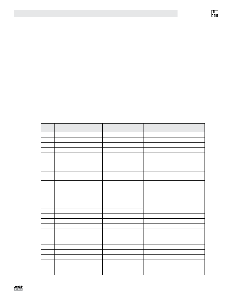
Table 5 describes the SMV Drive Con trol Registers in ascending order of SMV Register #. Registers #1 through #99
are reserved for configuration and control over the network and cannot be accessed via the drive’s local keypad.
Table 5: SMV Drive Control Registers
Reg #
Register Name
Default
Range of
Adjustment
Important
1
Drive Control (write only)
See Sections 8.1 and 9.2.1
19
Drive Family
Read only, drive family is 72
21
Drive Size
Read only. See section 9.2.2
23
Drive Status
Read only. See section 9.2.3
24
Command Frequency
0.0 Hz
0.0 … 500.0
Read only.
25
Actual Frequency
0.0 Hz
0.0 … 500.0
Read only.
26
Load (DH)
Run Status (DL)
Read only. See section 9.2.4
Read only. See section 9.2.5
27
Actual Direction (DH)
Control Mode (DL)
Read only. See section 9.2.6
Read only. See section 9.2.7
28
Speed Source (DH)
Auto/Manual (DL)
Read only. See section 9.2.8
Read only. See section 9.2.9
29
Present Fault (DH)
Commanded Direction (DL)
Read only. See section 9.2.10
Read only. See section 9.2.11
30
Motor Voltage
Read only. See P506 in drive manual
32
Total kWh (low word)
Read only. See P511 in drive manual
33
Total kWh (high word)
37
Actual PID setpoint
0.0
-999.0 … 3100.0
Read only. See section 9.2.12
38
PID Setpoint Command
0.0
-999.0 … 3100.0
Read only. See section 9.2.12
39
PID Feedback
0.0
-999.0 … 3100.0
Read only. See section 9.2.12
40
Keypad Speed Command
20.0 Hz
P102 … P103
41
Keypad PID Setpoint Command
0.0
-999.0 … 3100.0
Read only. See section 9.2.12
42
Keypad Torque Command
100%
0.0 … 400.0
44
Network Speed Command
0.0 Hz
P102 … P103
See Section 8.3
45
Network PID Setpoint Command
0.0
-999.0 … 3100.0
Read-only See Sections 8.3 and 9.2.12
46
Network Torque Command
0%
0.0 … 400.0
See Sections 8 3
48
Unlock Controls
See Sections 7 3
49
Unlock Parameters
See Sections 7 3
50
Parameter Version
Read only. See section 9.2.13