Installation, Figure 4: connector wiring diagram – Lenze ESVZAR0 RS-485 User Manual
Page 10
8
CMVMB401C
Installation
3.2
RS-485 Terminal Block
Table 3 describes the RS-485 terminal block. The 5 pole connector provides 2-wire connection to the network.
Table 3: RS-485 Terminal Block
Terminal Description
Important
Connector
1
Earth ground /
shield
For reliable communication make sure terminal is
connected to the Modbus network GND/common.
If only two wires are used (TXA and TXB) in the
network, connect Terminal 1 to chassis/earth GND.
1 2
3 4
5
2
TXA
If controller is located at either end of the network,
a terminating resistor (120ohm typical) should be
connected across TXA and TXB
3
No connection
4
TXB
5
No connection
Protection against contact
• All terminals have basic isolation (single insulating distance)
• Protection against contact can only be ensured by additional measures (i.e. double insulation)
3.3
Electrical Installation
3.3.1 Cable Types
For RS-485 Modbus networks, use a quality shielded twisted pair cable. The use of low quality cable will result in
excess signal attenuation and data loss.
3.3.2 Connections and Shielding
To ensure good system noise immunity all networks cables should be correctly grounded:
• Minimum grounding recommendation: ground the network cable once in every cubical.
• Ideal grounding recommendation: ground the network cable on or as near to each drive as possible.
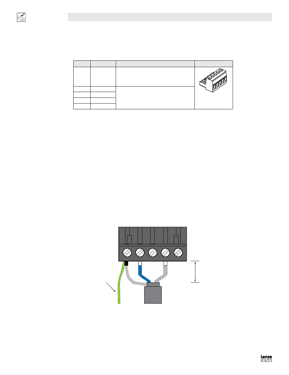
• For wiring of cable to the connector plug the unscreened cable cores should be kept as short as possible;
recommended maximum of 20mm. The shield connection of terminal 1 should also be wired to earth (PE).
20mm
max
Connect to
drive earth
(PE)
1
2
3
4
5
Figure 4: Connector Wiring Diagram