Bunn TNTF-3 User Manual
Page 25
Page 25
SERVICE (cont.)
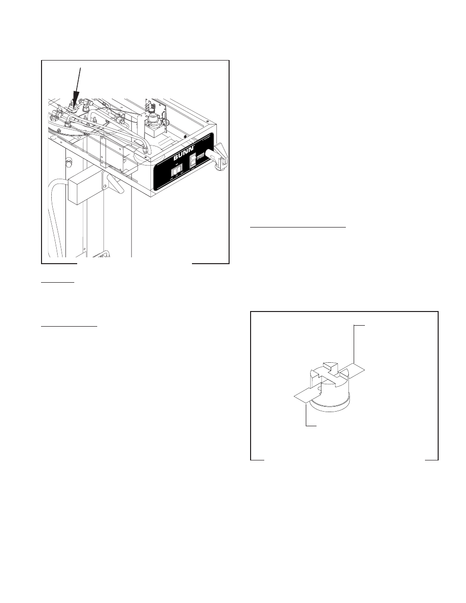
LIMIT THERMOSTAT
FIG. 18 LIMIT THERMOSTAT
P2213.60
Location:
The limit thermostat is located inside the hood on
the tank lid.
Test Procedure:
1. Disconnect the brewer from the power source and
remove the black wire from the limit thermostat.
2. With a voltmeter, check the voltage across the
black wire removed from the limit thermostat and
the white wire or red wire on the tank heater ter-
minal. Connect the brewer to the power source.
The indication must be:
a) 120 volts ac for two wire 120 volt models.
b) 208 volts ac for three wire 120/208 volt mod-
els.
3. Disconnect the brewer to from the power source.
If voltage is present as described, reconnect the black
wire and proceed to #4.
If voltage is not present as described, refer to the
Wir-
ing Diagram
and check the wiring harness.
4. Remove the blue wire from the limit thermostat.
5. With a voltmeter, check the voltage across the ex-
posed terminal of the limit thermostat and the
white wire from the power cord or the red wire
from the terminal block. Connect the brewer to
the power source. The indication must be:
a) 120 volts ac for two wire 120 volt models.
b) 208 volts ac for three wire 120/208 volt mod-
els.
6. Disconnect the brewer from the power source.
If voltage is present as described, reconnect the blue
wire to the limit thermostat. The limit thermostat is
operating properly.
If voltage is not present as described, replace the limit
thermostat.
Removal and Replacement
1. Remove both wires from the limit thermostat ter-
minals.
2. Carefully slide the limit thermostat out from un-
der the retaining clip.
3. Carefully slide the new limit thermostat into the
retaining clip.
4. Refer to Fig. 19 when reconnecting the wires.
BLU to
Control
Thermostat
BLK to Power Cord
or Terminal Block
FIG. 19 LIMIT THERMOSTAT TERMINALS
P1800
28201 081598