Atx pass-through lead, Power connection, Fan connection – Koolance RP-985 User Manual
Page 8: Temperature sensor placement
8
9
User Manual
Installation
ATX Pass-Through Lead
The ATX pass-through lead
is responsible for sending the
shut-down signal if any sensor
reaches the preset shutdown
temperature (See Display Panel
for configuration).
There is no polarity direction with
the ATX lead. Connect the male
ATX power lead from the cooling
unit to your computer’s main
chassis power button.
Connect the female ATX power lead from
the Slot Adapter to the motherboard’s
power switch connection (often marked
“PWRSW”, “PWSW”, or “PWBT”).
This is the connection that would normally
receive the chassis power button
directly.
CAUTION
:
The auto shutdown safety feature of this product will not
function without properly connecting the ATX pass-through lead.
!
To Motherboard
Chassis Power
Button
From Cooling
Unit
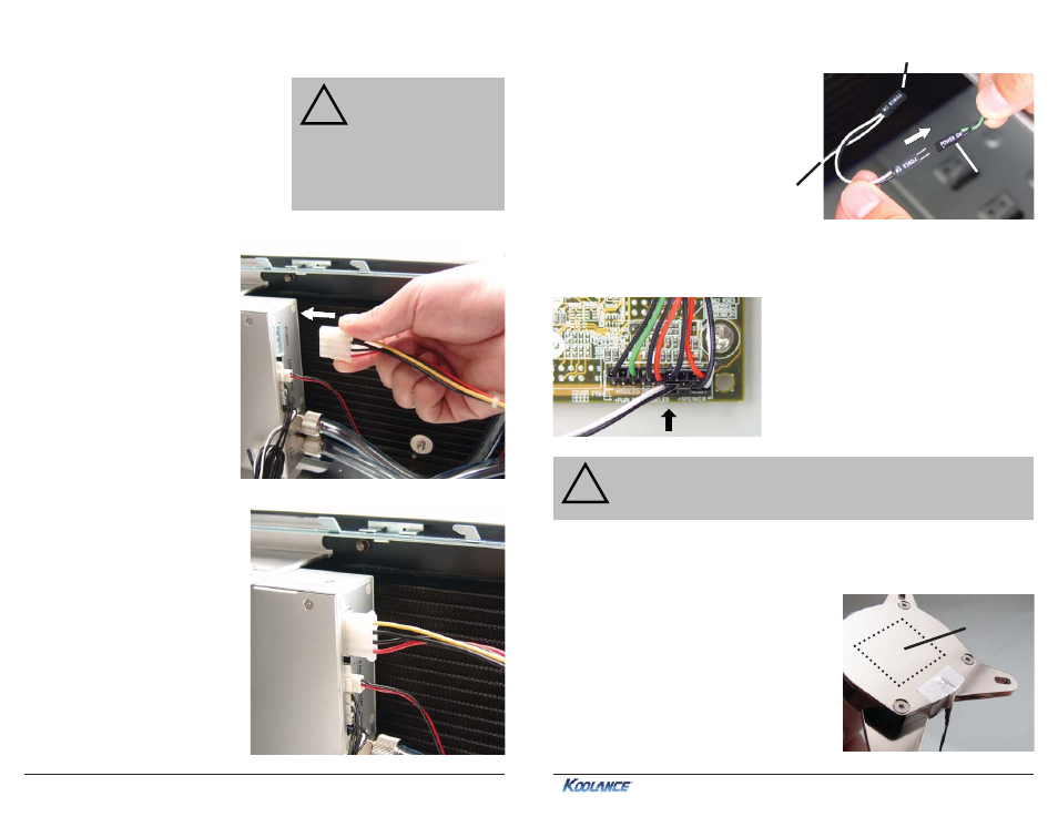
Power Connection
The temperature sensors and ATX
lead may come pre-connected to
your unit. If not, connect them per
the diagram on page 7.
Connect a 12 Volt 4-pin Molex
plug from the power supply to the
power connection on the rear of
the unit.
Fan Connection
This unit has two connections to power
radiator fans. Multiple fans can be combined
into a single plug. (A fan wiring harness is
optionally available from Koolance).
CAUTION
:
The total
combined amperage
of all fans connected to
the unit can not exceed
3A. The maximum load
on a single fan header
is 2.0A.
!
Temperature Sensor Placement
Three surface temperature sensors are
included with this product for monitoring.
Generally, sensors are affixed to water
blocks with metal tape. (Liquid temperature
sensors are also available optionally from
Koolance.)
Sensors should never be placed directly
between a heat source and its water block.
This will interfere with contact and can
damage the sensor or heat source.
Chip contact
area
(keep out)