Sheet2, Drawing view1, Drawing view2 – Kargo Master EZ Lo-Down Driver Side Mechanism (40863) User Manual
Page 8: Drawing view4, Step 8, Diagram 12, Step 9
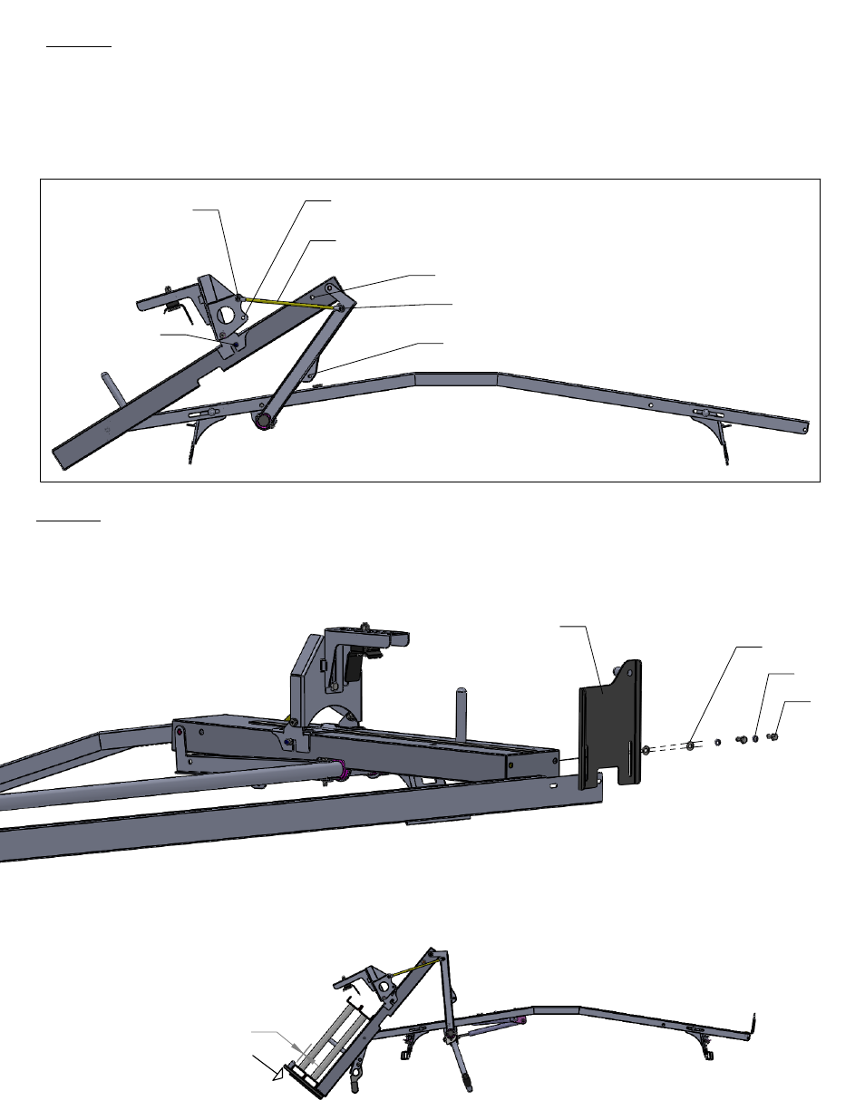
STEP 8
Install link rods. Depending on the location of the hinge bracket assembly (-006),
location #1 will require link rod to attach to hole "E" and "H" per [DIAGRAM 12].
Location #2 (which is step ladder wide end) will require the link rod to attach to
hole "F" and "G". Note: Hole "H" is threaded to allow rod end to screw directly into
bracket. All other holes will require 1each 5/16 flat washer (k) and 1each 5/16
nylock nut (h).
Hole "H"
Hole "G"
Hole "E"
Link Rod
Hole "F"
DIAGRAM 12
Location #2
Location #1
STEP 9
I
nstall hold down plates (-008) and ladder pan stiffener(-031) using 4 each 5/16 flat
washers (K), 4 each 5/16 lock washers (p) and 4 each 5/16 x 3/4 hex bolts (s) only
after assembly is complete. Hand tighten hardware.
Hold Down Plate
(-008)
(k)
(p)
(s)
Next position the front hold down plate (-008) approximately 1/8" from top of the
ladder side channel. This gap will ensure the ease of ladder insertion into the front
ladder pan. Bring rear hold down plate in slight contact with side channel (rear
should be snug to prevent ladder movement in transport). Now tighten hardware.
1/8"
Front