Drawing view200, Drawing view214, Drawing view216 – Kargo Master Clamp & Lock Curb Side (40803) User Manual
Page 8: Detail view bk (1 : 18), Step 12, Diagram 8, Diagram 7, Diagram 7a step 11
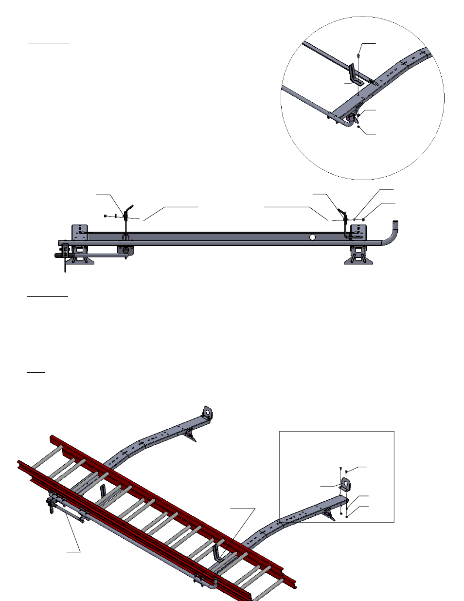
Clamp Pads
(-034)
(b)
(c)
Tube Assemby
(-020)
Pad Bracket
(-026)
STEP 12
Now install ladder into desired position with ladder rung firmly against the clamp
pads. Now adjust front pad bracket (-026) firmly against rung. It may be
necessary to move pad bracket (-026)to align with one of the two square holes
in the cross bow. Note: position pad bracket (-026) so adequate pressure is
applied to ladder rung when rotating handle (-002). Ladder should be clamped
firm with no movement when handle is in lock position. Tighten all hardware.
You may want to install load lock plate (-025) using 4 each 5/16 x 3/4 carriage
bolts (f), 4 each 5/16 flat washers (k), and 4 each 5/16 nylock nuts (h) per
[DIAGRAM 8].
(a)
(k)
(h)
Load Lock
Plate
(-025)
DIAGRAM 8
Pad Bracket
(-026)
Handle
(-002)
For TECHNICAL SUPPORT Call: 800-343-7486
BK
DIAGRAM 7
(a)
(b)
(c)
Pad Bracket
(-026)
DIAGRAM 7a
STEP 11
Install pad bracket (-026) using 1 each 3/8 x 1
carriage bolt (a), 1each 3/8 flat washer (b), 1
each 3/8 nylock nut (c) shown in [DIAGRAM 7].
Do not tighten for later adjustment.
Now install the clamp pads (-034) to pad
bracket (-026) and tube assembly (-020) per
[DIAGRAM 7a] using 2 each 3/8 washers (b)
and 2 each 3/8 nylock nuts (c). Do not tighten.