Drawing view169, Detail view bc (1 : 8), Drawing view171 – Kargo Master Clamp & Lock Curb Side (40803) User Manual
Page 6: Detail view be (1 : 8), Drawing view173, Drawing view174, Detail view bf (1 : 8), Diagram 4 diagram 3, Step 7, Step 8
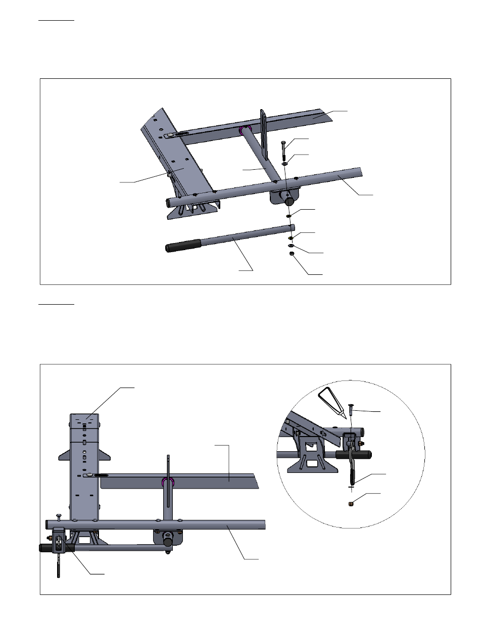
BC
Support Angle
(-014)
Side Tube
(-012)
Cross Bow
(-001)
Handle
(-002)
(g)
(-038)
(h)
(k)
(k)
(-038)
Tube
Assembly
(-016)
BE
Lock Box Assembly
(-002)
E6000
Rear View
Front View
Side Tube
(-012)
Angle Support
(-014)
Cross Bow
(-001)
DIAGRAM 4
DIAGRAM 3
BF
(u)
(w)
(k)
STEP 7
Next, install handle (-002) to the end of tube assembly (-016) using 1 each
5/16 x 2 3/4 hex bolt (g), 2 each nylon washers (-038), 2 each 5/16 flat washers
(k), 1 each 5/16 nylock nut (h). Note: insert washers (-038 ) over and under
handle tube (-002) per [DIAGRAM 3]. Tighten so handle rotates freely.
STEP 8
Install the lock box assembly (-002) to the end of the side tube (-012) per
[DIAGRAM 4] Using 1 each 5/16 x 1 1/2 carriage bolt (u), 1 each 5/16 washer
(k), 1 each 5/16 nylock jam nut (w). Run a bead around the bolt head with
E6000 as shown.