Drawing view160, Detail view ar (1 : 5), Drawing view162 – Kargo Master Clamp & Lock Curb Side (40803) User Manual
Page 5: Detail view av (1 : 4), Drawing view165, Detail view bb (1 : 8), Drawing view167, Drawing view168, Diagram 2a, Diagram 2b
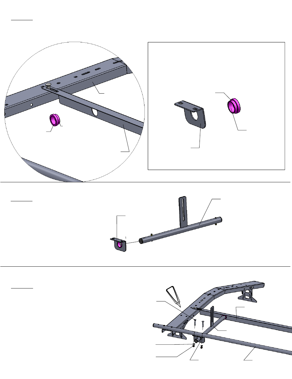
AR
Bushing
(-013)
Support Angle
(-014)
DIAGRAM 2a
Cross Bow
(-001)
Flange Side
DIAGRAM 2b
Bushing
(-013)
AV
Flange Side
Bracket Plate
(-015)
BB
STEP 5
Install bracket plate
(-015) with the
flange facing
outward onto tube
assemby (-016)
as shown.
Bracket
Plate (-015)
Tube Assembly
(-016)
(u)
(k)
(h)
Side Tube
(-012)
Bracket Plate
(-015)
Angle Support
(-014)
Tube Assembly
(-016)
E6000
STEP 4
Next, insert bushing (-013) into support angle (-014) flange side in per [DIAGRAM 2a].
Next, insert bushing (-013) into bracket plate(-015) as shown in [DIAGRAM 2b].
STEP 6
Now install the end of tube
assembly (-016) into the bushing
on the support angle (-014).
Match up the holes in the bracket
plate (-015) to the holes in the side
tube (-012 ) and insert 2 each 5/16 x
1 3/4 carriage bolts (u), 2 each 5/16
flat washers (k) and 2 each 5/16
nylock nuts (h). Run a bead of E6000
around the head of the bolts.