Connection diagram dimensions block diagram, Function – JUMO 902910 CANtrans T RTD Temperature Probe with CANopen Output Data Sheet User Manual
Page 3
2010-06-11/00418901
Data sheet 90.2910
Page 3/4
JUMO GmbH & Co. KG
Delivery address: Mackenrodtstraße 14,
36039 Fulda, Germany
Postal address:
36035 Fulda, Germany
Phone:
+49 661 6003-0
Fax:
+49 661 6003-607
E-mail:
Internet:
www.jumo.net
JUMO Instrument Co. Ltd.
JUMO House
Temple Bank, Riverway
Harlow - Essex CM20 2DY, UK
Phone: +44 1279 63 55 33
Fax:
+44 1279 63 52 62
E-mail:
Internet: www.jumo.co.uk
JUMO Process Control, Inc.
8 Technology Boulevard
Canastota, NY 13032, USA
Phone:
315-697-JUMO
1-800-554-JUMO
Fax:
315-697-5867
E-mail:
Internet: www.jumo.us
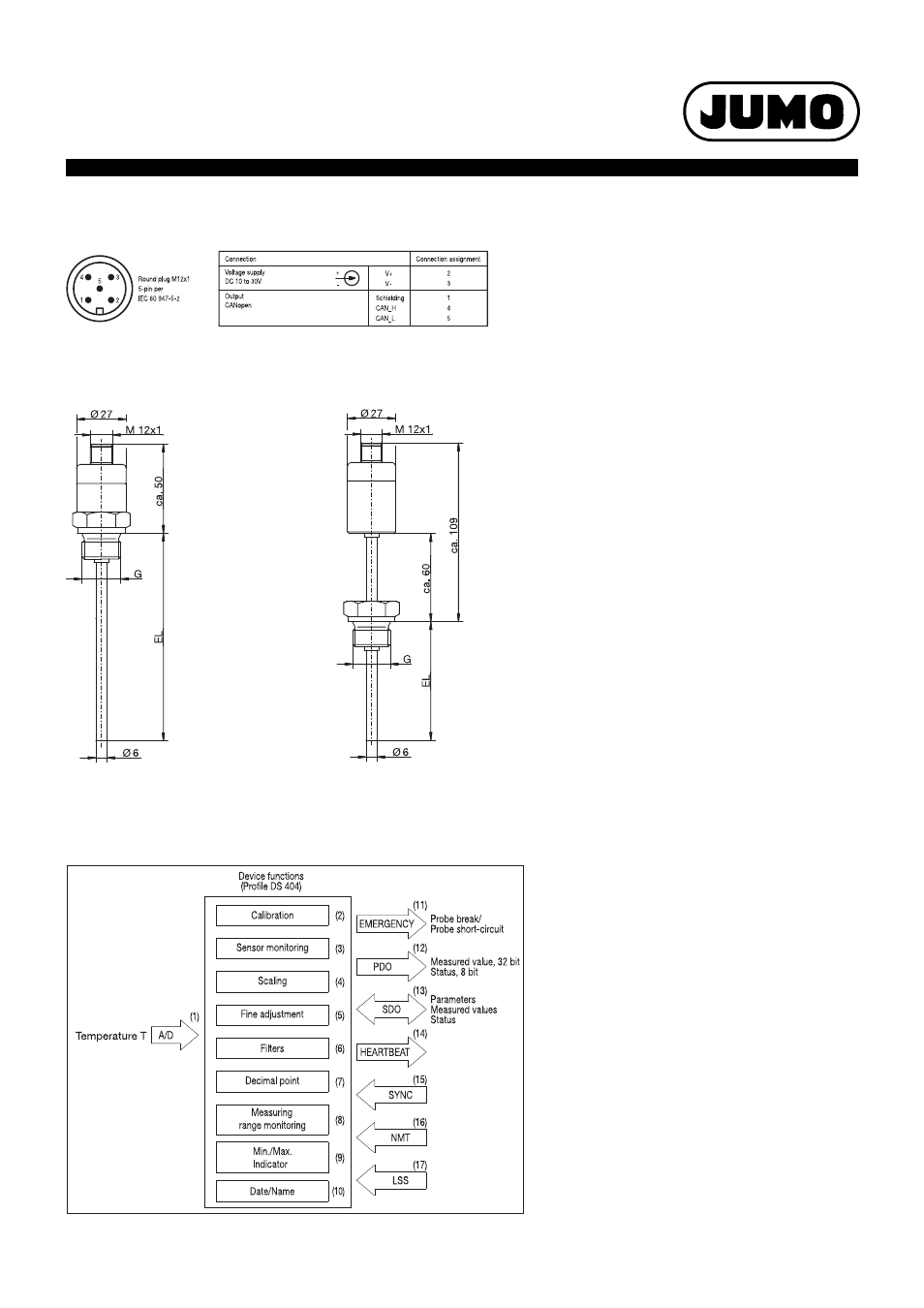
Connection diagram
Dimensions
Block diagram
Type 902910/10
Type 902910/12
Function
(1)
The measured temperature value is dig-
itized.
(2)
The temperature signal is digitally facto-
ry adjusted.
(3)
The probe monitoring system perma-
nently checks the correct function of
the probe signal and initiates high-prior-
ity emergency telegrams in the event of
an error.
(4)
The measured temperature value can
be scaled to any measuring unit (or as
% of the measuring range).
(5)
The precise adjustment has a freely set-
table characteristic curve offset.
(6)
Undesirable signal fluctuations can be
suppressed using the configurable filter
constant.
(7)
The measured value is transmitted with
a freely selectable decimal place.
(8)
The measuring range monitoring has
freely selectable upper and lower limits.
The result is transmitted as a status
byte in addition to the measured value
in the PDO telegram.
(9)
The fly back function saves the mini-
mum and maximum measured temper-
ature value.
(10)
Date and name of the last maintenance
work can be saved.
(11)
The emergency telegram is initiated in
the event of a defective probe.
(12)
The PDO telegram contains the 32 bit
measured value and the 8 bit status.
The measured value output can be con-
trolled via various trigger conditions.
(13)
SDO telegrams can be used to set pa-
rameters as well as request measured
values and the status.
(14)
The heartbeat signal can be used to ad-
ditionally monitor the function of the
transducer.
(15)
The Sync command can be used to ad-
ditionally control measured value trans-
mission.
(16)
The NMT telegrams serve to control the
operating status of the transducer.
(17)
The CAN module ID and the CAN baud
rate are set optionally via LSS or SDO.