Connections – JUMO 707530 Ex-i Repeater Power Supply / Input Isolating Amplifier Data Sheet User Manual
Page 3
2012-08-22/00584206
Data Sheet 707530
Page 3/4
JUMO GmbH & Co. KG
Telefon: +49 661 6003-727
Hausadresse:
Moritz-Juchheim-Straße 1, 36039 Fulda, Germany
Telefax: +49 661 6003-508
Lieferadresse:
Mackenrodtstraße 14, 36039 Fulda, Germany
E-Mail:
Postadresse:
36035 Fulda, Germany
Internet: www.jumo.net
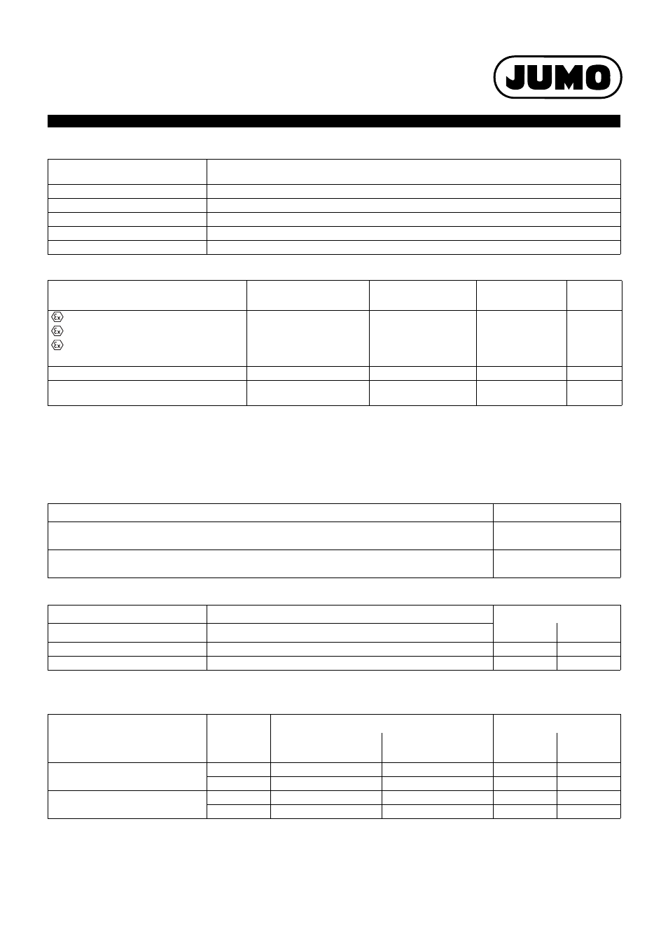
Approvals/approval marks
Connections
The connection diagram in the data sheet provides preliminary information about the connection possibilities. Only use the operating manual for
the electrical connection. The knowledge and the correct technical execution of the safety information/instructions contained in these documents
are mandatory for installation, electrical connection, and commissioning/start-up as well as for safety during operation.
Input (Ex-i)
Output of current without HART communication
Output of current with HART communication
Conductor cross section AWG/kcmil
max.
14
Stripping length
8 mm
Thread
M3
Connection type
Screw connection
Tightening torque min.
0.5 Nm
Tightening torque max.
0.6 Nm
Approval marks
Testing agency
Certificates/
certification numbers
Inspection basis
Valid for
II (1) G [Ex ia Ga] IIC/IIB
DEKRA
BVS 12 ATEX E 090 X
EN 60079-0:2009
II (1) D [Ex ia Da] IIIC
EN 60079-11:2012
II 3 (1) G Ex nA [ia Ga] IIC/IIB T4 Gc
EN 60079-15:2010
EN 60079-26:2007
SIL2
DEKRA
EN 61508
UL us
Underwriters Laboratories
E354603
C.D.-No 83135047
UL 61010-1
UL 913
USA
Connection for
Terminals
Supply isolating amplifier mode
4.1 (+) and 4.2 (-)
(2-wire transmitter)
Input isolating amplifier mode
4.2 (+) and 4.3 (-)
(4-wire transmitter or power sources)
Connection for
Terminals
DIP-switch position
a
a
The two DIP-switches are located at the front of the device. Settings made to the device with DIP switches must occur in a voltage-free state.
S1
S2
Source (passive input card)
3.1 (+) and 3.2 (-)
I
II
Sink (active input card)
3.2 (+) and 3.3 (-)
I
II
Connection for
Electrical cir-
cuit
impedance
Connection
DIP-switch position
a
a
The two DIP-switches are located at the front of the device. Settings made to the device with DIP switches must occur in a voltage-free state.
of the input card
at terminal
of the HART
communicator
S1
S2
Source (passive input card)
≥ 250 Ω
3.1 (+) and 3.2 (-)
3.1 and 3.2
I
II
< 250 Ω
3.1 (+) and 3.2 (-)
3.2 and 3.3
I
I
Sink (active input card)
≥ 250 Ω
3.2 (+) and 3.3 (-)
3.2 and 3.3
I
II
< 250 Ω
3.2 (+) and 3.3 (-)
-
I
II