Mounting the control station, Calibrate the analog output voltage level – Johnson Systems CS-SA Series Time Fade Stations User Manual
Page 8
8
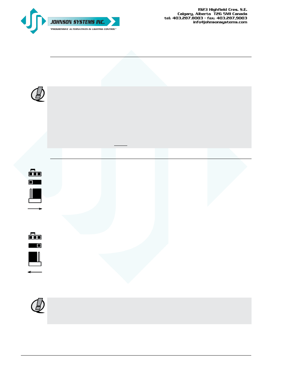
NORMAL
RUN
MODE
OUTPUT CAL
JP1
OUTPUT
CALIBRATION
MODE
OUTPUT CAL
JP1
JUMPER
JUMPER
Mounting the Control Station
The control station can be mounted on/in a gangable (usually masonry) type of back box
with a minimum depth of 2" (50.8mm) and a preferred depth of 3.5” (88.9mm). A #2 Phillips
head screwdriver is required to secure the control station, using the provided black #6-32 x 1"
(25.4mm) mounting screws.
NOTE: Ensure the back box is earth grounded to protect the control station from electrostatic
discharge.
NOTE: Ensure the back box mounting-hole threads are not damaged. Damaged threads on the
back box can damage the threads on the mounting screws and cause stripping. The back
box threads can quickly be cleaned up by running a #6-32 tap through the mounting hole.
Be sure not to over-tighten the mounting screws or this could result in stripping the back
box mounting-hole threads.
NOTE: For applications other than 0 to 10VDC analog output control, the analog output voltage
needs to be calibrated before the control station is mounted. See below for details.
Calibrate the Analog Output Voltage Level
Calibration of the analog output voltage should be completed at the time of installation. The analog
output may need to be calibrated for line loss or to change the analog output voltage range.
The analog output voltage can be calibrated/adjusted for analog control over a range from
0 to 22VDC (24VDC power supply) in 12-bit step resolution for precise control and calibration.
The analog output voltage is factory set for 0 to 10VDC control.
Ensure the power supply voltage is a minimum of 2VDC greater than the required analog output
voltage.
Procedure:
• Set the output calibration (OUTPUT CAL) jumper (JP1) in the left-hand side position.
• Set the master slider potentiometer (pot) in the full on position (all the way up).
• Measure the DC voltage between common (COM) and the master pot (MP) output.
• Press the “ON” button to increase the analog output voltage. The “ON” LED illuminates when
the button is pressed. Press and hold the “ON” button to accelerate the voltage adjustment.
• Press the “OFF” button to decrease the analog output voltage. The “OFF” LED illuminates
when the button is pressed. Press and hold the “OFF” button to accelerate the voltage
adjustment.
• Pressing the “ON” and “OFF” buttons at the same time adjusts the output voltage to
approximately 10VDC.
• Once the required output voltage has been measured, set the output calibration jumper back
in the right-hand side position to exit calibration mode and save the calibration setting.
NOTE: The control station will go into overload protection (all button LED’s flash on and off) if the
output voltage calibration is set higher than the power supply input voltage. If this occurs,
recalibrate the output voltage to a lower voltage. Ensure the power supply voltage is a
minimum of 2VDC greater than the required analog output voltage.