Cs-sa series control station diagrams – Johnson Systems CS-SA Series Time Fade Stations User Manual
Page 4
4
P1
P2
P3
P1
P2
P3
P1
P2
P3
J1
JP1
OUTPUT
CAL
P1
P2
P3
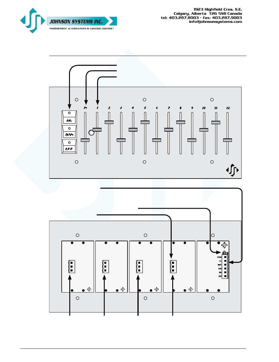
"ON", "DIM", and "OFF" Buttons With Integral LED's
Master (M) Slider
Secondary (3, 6, 9, or 12) Sliders
6-Position Connector (J1) For:
• Power Supply Input (COM, V+)
• Button Contacts (ON, DIM, RST)
• Master Pot (MP) Analog Output
Analog Output Voltage Level Calibration Jumper (JP1)
Analog Output Connector(s)
Analog
Outputs
10, 11, 12
Analog
Outputs
7, 8, 9
Analog
Outputs
4, 5, 6
Analog
Outputs
1, 2, 3
CS-SA Series Control Station Diagrams