Johnson Systems CS-SA Series Time Fade Stations User Manual
Page 7
7
COM
V+
ON
DIM
RST
COM
V+
ON
DIM
RST
COM
V+
RST
MP
COM
V+
RST
MP
P1
P2
P3
P4 (P1)
P5 (P2)
P6 (P3)
P7 (P1)
P8 (P2)
P9 (P3)
P10 (P1)
P1
1 (P2)
P12 (P3)
P1
P2
P3
P4 (P1)
P5 (P2)
P6 (P3)
P7 (P1)
P8 (P2)
P9 (P3)
P10 (P1)
P1
1 (P2)
P12 (P3)
COM
V+
CS-SA-12
DC POWER SUPPLY
COMMON (V-) INPUT
DC POWER SUPPLY
POSITIVE (V+) INPUT
ANALOG OUTPUTS
COM
V+
RST
COM
V+
RST
CS-SA-12
DC POWER SUPPLY
COMMON (V-) INPUT
DC POWER SUPPLY
POSITIVE (V+) INPUT
ANALOG OUTPUT
CS-SA-1
CS-SA-1
COM
V+
MP
COM
V+
ON
RST
COM
V+
ON
RST
P1
P2
P3
P4 (P1)
P5 (P2)
P6 (P3)
P7 (P1)
P8 (P2)
P9 (P3)
P10 (P1)
P1
1 (P2)
P12 (P3)
P1
P2
P3
P4 (P1)
P5 (P2)
P6 (P3)
P7 (P1)
P8 (P2)
P9 (P3)
P10 (P1)
P1
1 (P2)
P12 (P3)
COM
V+
CS-SA-12
DC POWER SUPPLY
COMMON (V-) INPUT
DC POWER SUPPLY
POSITIVE (V+) INPUT
ANALOG
OUTPUTS
CS-SA-12
DC POWER SUPPLY
COMMON (V-) INPUT
DC POWER SUPPLY
POSITIVE (V+) INPUT
ANALOG OUTPUT
CS-SA-ENT2B
CS-SA-ENT2B
COM
V+
MP
ANALOG
OUTPUTS
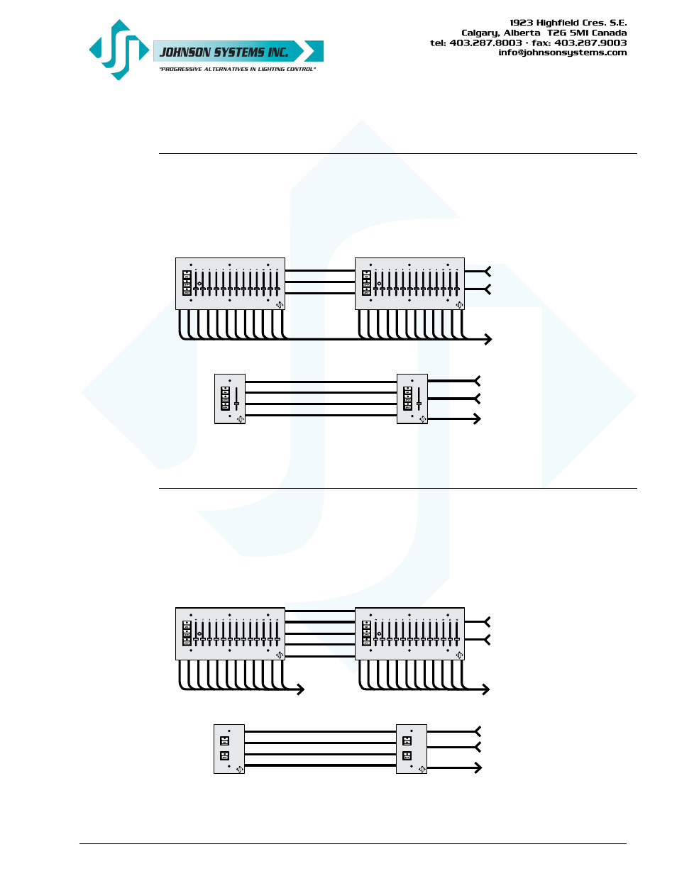
Wiring Two or More Master Control Stations
Together with “Take Control”
When two or more master control stations are controlling the same device, “take control”
is typically required. When a button is pressed on one of the master control stations, it will
automatically “take control” from the other master control stations and put them in the “OFF”
state. Wiring between the master control stations requires 2 conductors for V+ and common,
and 1 conductor for reset (RST) “take control”.
Wiring Two or More Control Stations
Together with “Mimic”
“Mimic” refers to pressing a button (“ON”, “DIM” or “OFF”) on a control station, and the other
control station(s) are automatically triggered into the same “ON”, “DIM” or “OFF” state. The
analog output(s) could be controlling the same device or completely different device. Wiring
between the control stations requires 2 conductors for V+ and common, and 3 conductors (2
conductors for Part Number: CS-SA-ENT2B) for the switches (ON, DIM and RST), 1 conductor
for each switch function.