On”, “dim” and “off” buttons with integral led’s, Master (m) slider, Power supply requirement – Johnson Systems CS-SA Series Time Fade Stations User Manual
Page 5: Control station wiring
5
“ON”, “DIM” and “OFF” Buttons with Integral LED’s
All CS-SA Series control stations contain 3 buttons with integral blue LED’s. When a button
is pressed, the control station is triggered into the corresponding state. The button LED’s
indicate the state of the control station. Under normal operation, when a button is pressed, the
corresponding LED will illuminate. If the control station is fading, the LED will flash once per
second until the fade is complete. Pressing a button or adjusting the master slider level while
the control station is fading, cancels the fade and immediately activates the button pressed. The
button LED’s also indicate when local or remote lockout is active, or if there is a short-circuit or
overload condition (refer to page 10 for details). The intensity of the button LED’s can be adjusted
(refer to “Set the Button LED Intensity” on page 9).
Pressing the “ON” button triggers all of the analog output levels to full on. The “ON” button
corresponds with the “ON” connection on J1 and is optionally connected to other control stations
for various applications.
Pressing the “DIM” button activates analog output control from the slider potentiometers (pots).
The “DIM” button corresponds with the “DIM” connection on J1 and is optionally connected to
other control stations for various applications.
Pressing the “OFF” button turns off (zero output level) all of the analog outputs. The “OFF” button
corresponds with the “RST” (reset) connection on J1 and is optionally connected to other control
stations for various applications.
Master (M) Slider
The master slider controls the overall maximum analog output level for all the secondary sliders,
as well as the analog output level on the master pot (MP) connection on J1. The master pot (MP)
analog output is capable of sourcing up to 50mA of current.
Secondary (3, 6, 9 or 12) Sliders
Each of the secondary sliders control the analog output level on each of the analog output (P#)
connections on the 3-position connector(s). Each analog output is capable of sourcing up to
50mA of current.
Power Supply Requirement
The control station requires a regulated DC power supply from 10.6VDC to 18VDC. The power
supply voltage should be a minimum of 2VDC greater than the required analog output voltage,
with the exception of 10.6VDC power supply applications with 0 to 10VDC analog output control
voltage. The power supply common (V-) connects to the “COM” connection on J1 and the power
supply positive (V+) connects to the “V+” connection on J1.
Control Station Wiring
CS-SA Series control stations can be wired for various analog applications. The control station
wiring can be configured for the functionality required.
Stranded, #18 AWG copper wire is recommended, however smaller gauge wire may be suitable
for some applications where distances are less than 150' (50m).
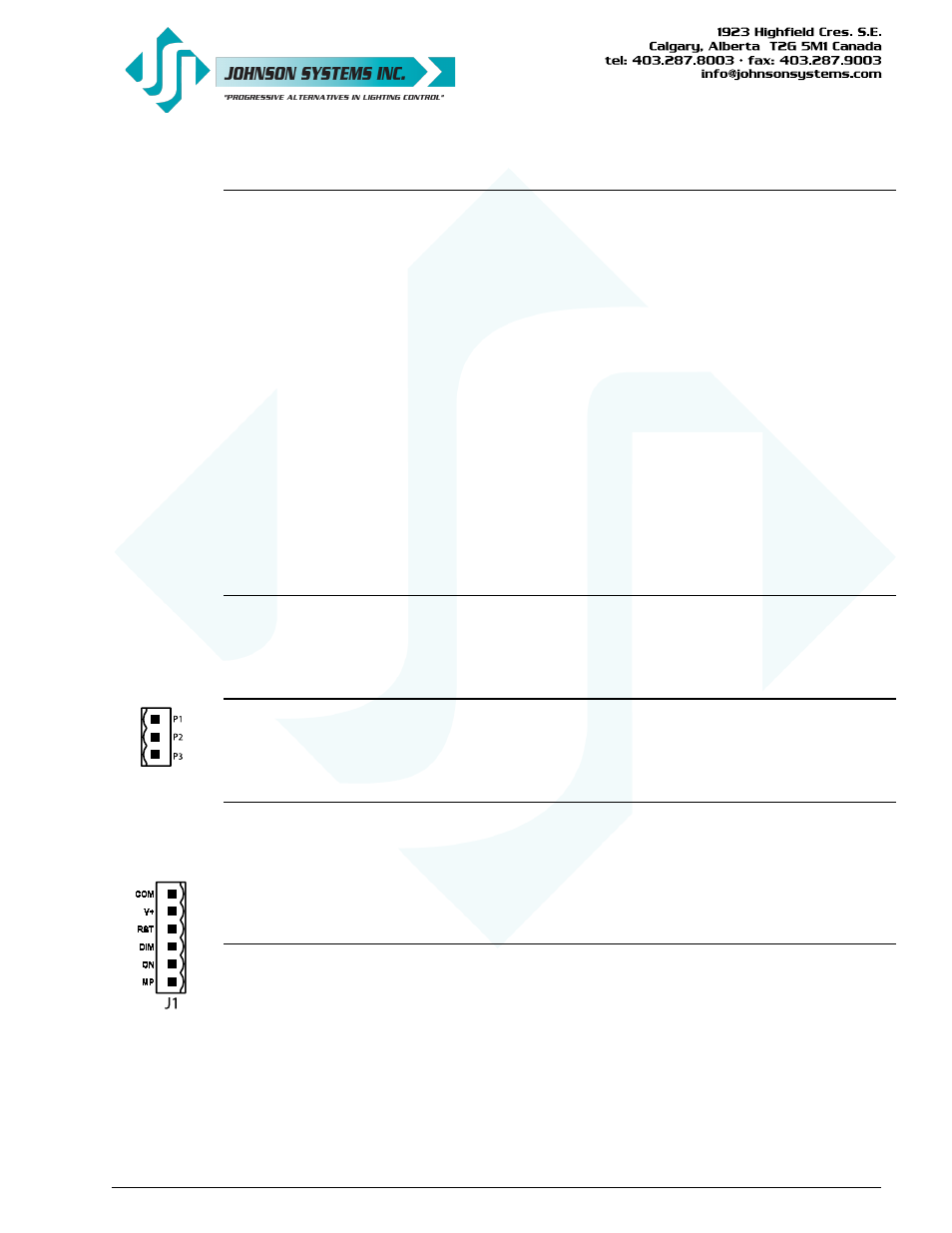
Breakaway connectors are provided for all wiring terminations. The 6-position connector (J1)
is used to connect the power supply (COM, V+), three switches (ON, DIM, RST), as well as
the master pot (MP) analog output. For 3, 6, 9 and 12 channel control stations, 3-position
connector(s) are used to connect the analog outputs (P#).
For proper termination, the strip length should be 0.28" (7mm). A 1/8" (3.2mm) flat head
screwdriver should be used to tighten the connections and torque to 3.5Lb-In (0.4Nm).