To a master control station, Wiring an independent control station – Johnson Systems CS-SA Series Time Fade Stations User Manual
Page 6
6
COM
V+
COM
V+
MP
COM
V+
MP
CS-SA-12
DC POWER SUPPLY
COMMON (V-) INPUT
DC POWER SUPPLY
POSITIVE (V+) INPUT
ANALOG OUTPUTS
DC POWER SUPPLY
COMMON (V-) INPUT
DC POWER SUPPLY
POSITIVE (V+) INPUT
ANALOG OUTPUT
DC POWER SUPPLY
COMMON (V-) INPUT
DC POWER SUPPLY
POSITIVE (V+) INPUT
ANALOG OUTPUT
CS-SA-1
CS-SA-ENT2B
P1
P2
P3
P4 (P1)
P5 (P2)
P6 (P3)
P7 (P1)
P8 (P2)
P9 (P3)
P10 (P1)
P1
1 (P2)
P12 (P3)
COM
V+
COM
V+
ON
DIM
RST
COM
V+
ON
DIM
RST
CS-SA-12
DC POWER SUPPLY
COMMON (V-) INPUT
DC POWER SUPPLY
POSITIVE (V+) INPUT
ANALOG OUTPUTS
CS-SA-ENT3B
CS-SA-ENT3B
P1
P2
P3
P4 (P1)
P5 (P2)
P6 (P3)
P7 (P1)
P8 (P2)
P9 (P3)
P10 (P1)
P1
1 (P2)
P12 (P3)
COM
V+
ON
DIM
RST
COM
V+
ON
DIM
RST
COM
V+
COM
V+
ON
RST
COM
V+
ON
RST
CS-SA-12
DC POWER SUPPLY
COMMON (V-) INPUT
DC POWER SUPPLY
POSITIVE (V+) INPUT
ANALOG OUTPUTS
CS-SA-ENT2B
CS-SA-ENT2B
P1
P2
P3
P4 (P1)
P5 (P2)
P6 (P3)
P7 (P1)
P8 (P2)
P9 (P3)
P10 (P1)
P1
1 (P2)
P12 (P3)
COM
V+
ON
RST
COM
V+
ON
RST
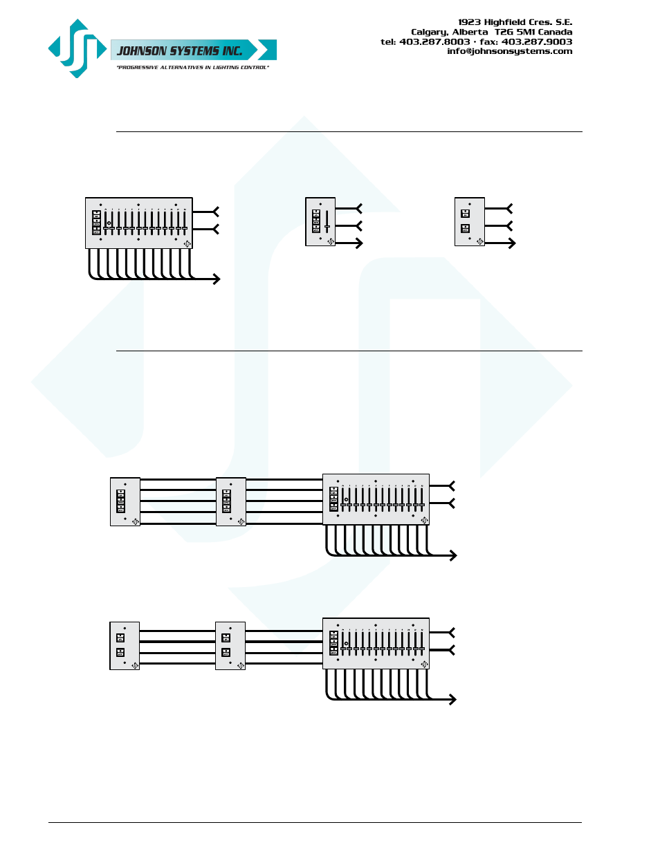
Wiring an Independent Control Station
An independent control station requires 2 conductors for V+ and common, and 1, 3, 6, 9 or 12
conductors for the analog outputs.
Wiring a Single or Multiple Entrance Control Stations
to a Master Control Station
An entrance control station (Part Numbers: CS-SA-ENT2B and CS-SA-ENT3B) is typically
installed at an entrance location and used to trigger a master control station into the “ON”, “DIM”
or “OFF” state. The entrance station(s) and master station mimic each other when a button
is pressed. Wiring between a single or multiple entrance stations and master station requires
2 conductors for V+ and common, and 3 conductors for the switches (ON, DIM and RST),
1 conductor for each switch function.