Troubleshooting, Frequently asked questions, Application tips – Intelix RF-F User Manual
Page 2
Troubleshooting
If your equipment malfunctions with RF baluns in place, follow the troubleshooting proce-
dures below:
1. Perform diagnostics on your video equipment by following the manufacturer’s
instructions.
2. Check all the connections and the structured cabling system. Verify the RJ45 crimp
pattern conforms to either EIA/TIA 568A or 568B standards.
3. Check the pin configuration on the structured cable.
4. The maximum operational distances over which the RF can be transmitted is
dependant on the equipment and cable used. Ensure that the maximum recommended
operational distances have not been exceeded.
5. If the picture is snowy, the signal strength may be insufficient. Increase the
signal power at the head-end using a tilt amplifier or use a higher grade cable.
6. If the picture is overly bright, the signal strength may be too great. Attenuate the
signal by reducing amplifier gain or by inserting a signal attenuator in the link.
7. Check that only twisted pair patch cords are being used.
8. Replace the RF balun with another RF that is known to be working.
9. If you still cannot diagnose the problem, contact Intelix for support.
Frequently Asked Questions
In a point-to-point scenario for CATV (superband and hyperband), VHF, and FM, cable
lengths of up to 150 feet may be achieved without amplification if the nominal input is about
15 dBm. In some applications, a tilt amplifier may be required since the Cat 5 cable losses are
higher than coax at the higher frequencies. Linear gain compensation of up to 20-25 dB at
750 MHz is usually adequate. Conversely, if amplification is used to compensate for losses at
high frequencies and longer distances, it may be necessary to attenuate the lower frequency
and shorter distance signals to avoid over-driving the TV monitors. The Intelix RF may be
used in conjunction with tilt/gain amplifiers, CATV splitters, and splitters with built-in ampli-
fiers. The following are some helpful guidelines when planning your cabling:
1.
Try for 10 dBmv of signal level at each television channel. Use a little more for big
screen TVs. Measure the signal level at the high and low end of the spectrum to
determine whether a tilt amplifier is needed.
2.
When laying out your system, there will be approximately 5dB of signal loss per 100' of
RG6-coaxial cable.
3.
Please ensure all splitters and amplifiers are broadband. For Cat 5 installations, splitters
should have 5 MHz to 900 MHz bandwidth with a bi-directional filter at 5 to 50 MHz.
4.
Check and make sure that all televisions are set up for the proper frequency spectrum
(i.e. UHF or cable).
5.
If extra channels are available, allow 1 to 2 channels spacing between “modulated” and
“active” channels.
6.
Always compensate for insertion loss with a good amplifier. There will always be a drop
in signal strength when combining a modulator to an existing system due to insertion
loss from the combiner.
7.
When combining an existing signal with a modulated signal, make sure to have equal
signal strength at the point of the combiner so one signal does not degrade the other.
8.
When possible, use the lowest frequencies available for the modulated channels. Lower
frequency channels have lower signal loss on the cable runs.
9.
When in doubt, run the signal a little high to the television and use an attenuator to lower
the signal strength going into the TV. Attenuators may be combined (i.e. two -3dB
attenuators will = -6dB).
10. Combine the modulator into the video distribution system as far “up-stream” as
possible.
11. If the system needs to be amplified, use the amplifier as far “up-stream” as possible. For
example, place one amplifier at the head end and one tilt amplifier in each wiring closet
where the baluns are located.
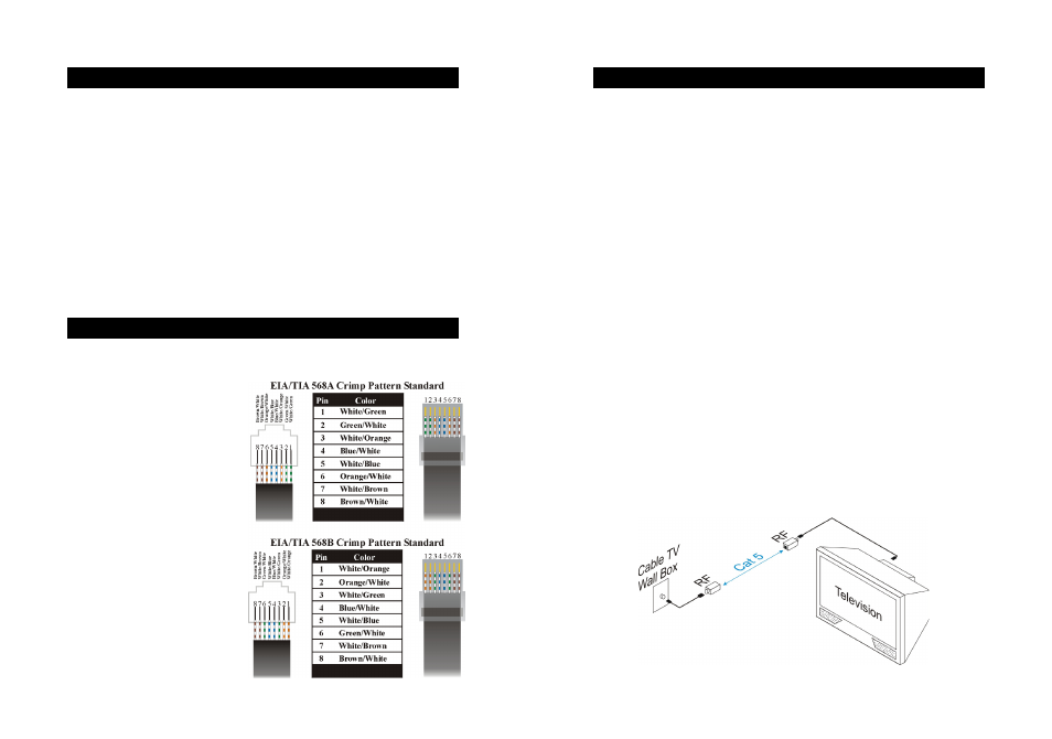
How do I crimp an unshielded RJ45 connector onto Cat 5?
Crimping an RJ45 connector onto Cat 5 is a fairly straight-forward task, assuming you have
the proper tools. Keep in mind that baluns require either the EIA/TIA 568A or 568B crimp
pattern, which are the industry standards
for networking.
1. First, strip a portion of the
insulation about 3/4" to expose the
four twisted pairs.
2. Next, untwist the wires and fan
them out so that they match
either the EIA/TIA 568A or 568B
pattern.
3. Evenly trim the wires to about
1/2". Most RJ45 crimp tools
feature a built-in wire trimmer.
4. Insert the trimmed wires into the
RJ45 connector so that each wire
is in its individual slot. Verify each
wire is completely inserted.
5. Finally, insert the RJ45 connector
into the crimp tool and squeeze
firmly.
6. Repeat the above steps on the
other end of the Cat 5 cable and
verify pinout is identical on each
end.
Application Tips
RF Example System Drawing