Operation, Deinstallation, Electrical connection – INFICON MPG40x ATM to Ultra-High Vacuum Gauge User Manual
Page 3: Gas type dependence, Ignition delay, Adjusting the gauge
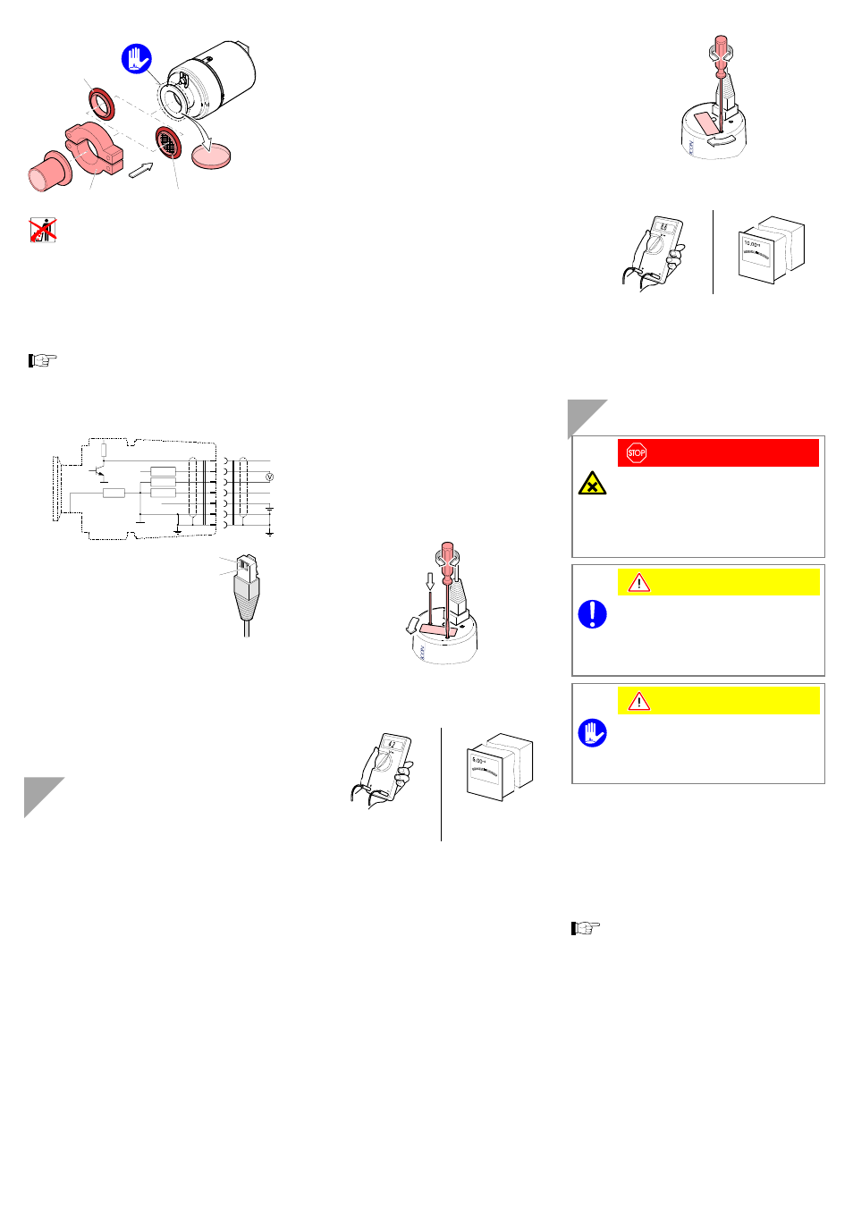
Seal with
centering ring
Clamp
or
Seal with centering ring
and filter
Protective lid
Keep the protective lid.
If adjustment should be possible after the gauge has been
installed, be sure to install it so that potentiometers
and
(
→
"Adjusting the Gauge").
Electrical Connection
Make sure the vacuum connection is properly
made (
→ "Vacuum Connection").
If no sensor cable is available, make one according to
the following diagram.
Electrical connection
Pin 1
Supply (15 … 30 VDC)
Pin 2
Supply common
Pin 3
Signal output
(measuring
signal)
Pin 4
Identification
Pin 5
Signal common
Pin 6
Status
Pin 7, 8 n.c.
8 poles FCC-68
1
8
10
10
Ident
3
5
4
1
2
–
+
–
+
6
10 k
Signal
Connect the gauge to the controller using the sensor
cable.
Operation
When the supply voltage is applied, the measuring signal is
available between pins 3 and 5. Over the whole measure-
ment range, the measuring signal is output as a logarithm of
the pressure (measuring signal vs. pressure
→ "Technical
Data").
Allow for a stabilizing time of
≈10 minutes. Once the gauge
has been switched on, permanently leave it on irrespective of
the pressure.
• The Pirani measurement circuit is always on.
• The cold cathode measurement circuit is controlled by the
Pirani circuit and is activated only at pressures
<1×10
-2
mbar.
Gas Type Dependence
The measurement value depends on the type of gas being
measured. The value displayed is accurate for dry air, O
2
,
CO and N
2
. It can be mathematically converted for other
gases (
→ "Technical Data").
If the gauge is operated in connection with an INFICON
vacuum gauge controller, a calibration factor can be entered
for correction of the reading.
Ignition Delay
When cold cathode measurement systems are activated
upon switching the gauge on, an ignition delay occurs, which
is typically:
10
-5
mbar
≈ 1 second
10
-7
mbar
≈ 20 seconds
5×10
-9
mbar
≈ 2 minutes
As long as the cold cathode measurement circuit has not yet
ignited, the measurement value of the Pirani is output as
measuring signal ("Pirani underrange" is displayed for pres-
sures <5×10
-4
mbar).
Adjusting the Gauge
The gauge is factory-calibrated. If used under different clima-
tic conditions, through extreme temperatures, aging or conta-
mination, and after exchanging the sensor, the characteristic
curve can be offset and readjustment may become
necessary.
The cold cathode measurement circuit, which is dominant for
low pressures (<1×10
-3
mbar), is factory-calibrated. By way of
contrast, the Pirani measurement circuit can be adjusted.
Any adjustment has a negligible effect on the pressure range
between approx. 10
-2
mbar and 10
2
mbar.
If you are using a seal with centering ring and filter,
check that they are clean or replace them if necessary
(
→ "Deinstallation").
Activate the gauge.
Evacuate it to p << 10
-4
mbar and wait at least
10 minutes.
Turn the nameplate counter-clockwise until the me-
chanical stop is reached.
While depressing the tactile switch with a cylindrical
pin (ø
≈
3 mm), adjust the
means of a 1.5 mm screwdriver …
… to 4.20 V
or
… to 5×10
-4
mbar
After that, turn the
potentiometer counter-
clockwise by
1/3
of a turn.
Vent the gauge with air or nitrogen to atmospheric
pressure, and wait at least 10 minutes.
Turn the nameplate clockwise until the mechanical stop
is reached.
Using the 1.5 mm screwdriver, adjust the
potentiometer …
… to 8.60 V
or
… to 1×10
3
mbar
Turn the nameplate back to its original position (it
catches).
Deinstallation
DANGER
DANGER: contaminated parts
Contaminated parts can be detrimental to health
and environment.
Before beginning to work, find out whether any
parts are contaminated. Adhere to the relevant
regulations and take the necessary precautions
when handling contaminated parts.
Caution
Caution: vacuum component
Dirt and damages impair the function of the
vacuum component.
When handling vacuum components, take ap-
propriate measures to ensure cleanliness and
prevent damages.
Caution
Caution: dirt sensitive area
Touching the product or parts thereof with one's
bare hands increases the desorption rate.
Always wear clean, lint-free gloves and use
clean tools when working in this area.
Vent the vacuum system.
Put the gauge out of operation and unplug the sensor
cable.
Remove the gauge from the vacuum system and place
the protective lid.
When deinstalling a CF flange connection, it can be
advantageous to temporarily remove the electronics
and the magnet unit (
→"Installation").