Operation, Power connection (hpg400), Gas type dependence – INFICON HPG400 ATM to High-Vacuum Gauge User Manual
Page 3: Measuring range, Selecting the changeover threshold, Adjusting the gauge (hpg400), Display
Remove the protective lid and install the product to the
vacuum system.
Keep protective lid
Clamp
Seal with
centering ring
Power Connection
(HPG400)
The following information on the electrical connec-
tion as well as the wiring diagram apply to HPG400
only (
→ [1] and [2] for details on the electrical
connection and additional functions of HPG400-SD
and -SP).
Make sure the vacuum connection is properly made
(
→ "Vacuum Connection").
If no sensor cable is available, make one according to
the following diagram.
Electrical connection
Pin 2 Signal output (measuring signal) 0 … +10 V
Pin 5 Supply common, GND
Pin 8 Supply +24 VDC
Pin 10 Gauge identifcation
Pin 12 Signal common, GND
Pin 13 RS232C, TxD
Pin 14 RS232C, RxD
Pin 15 Shielding, housing, GND
Pins 1, 3, 4, 6, 7, 9 and 11
are not connected internally.
8
9
1
15
TxD
HPG400
56kΩ
RxD
Measuring signal
+Ub
13
14
2
12
8
5
15
+
1.25AT
Identification
10
RS232C
+
24 V
D-Sub, 15-pin
female
soldering side
Connect the sensor cable to the gauge.
Secure the cable connector with the lock screws.
Connect the sensor cable to the controller.
Operation
When the voltage is supplied, the measuring signal is avail-
able between pins 2 (+) and 12 (–) (Relationship Measuring
Signal – Pressure
→ "Technical Data" and [1]).
HPG400-SD and -SP can also be operated via the corre-
sponding fieldbus interface (DeviceNet or Profibus) (
→ [1]
and [2]) for further details and functions).
Allow for a stabilizing time of
≈10 minutes. Once the gauge
has been switched on, permanently leave it on irrespective of
the pressure.
Gas Type Dependence
The measurement value is gas dependent. The displayed
reading applies to dry air, O
2
and N
2
. For other gases, it has
to be converted (
→ "Technical Data" and [1]).
Measuring Range
The HPG400 covers the measuring range
2×10
-6
mbar ... 1000 mbar.
• The Pirani part permanently monitors the pressure.
• The hot cathode part (controlled by the Pirani) is only
switched on when the pressure drops below the change-
over threshold. The hot cathode will be ready for operation
after a few seconds heating time, when the
lamp is lit.
• When the pressure rises above the changeover threshold,
the hot cathode is switched off and the
turns off.
In the upper pressure range, the Pirani reading and in the
lower pressure range, the hot cathode reading is output.
1000 mbar
2 ×
10
-6
mbar
Hot cathode HP
Pirani
5×10
-2
mbar ... 1 mbar user-
definable changeover threshold
Selecting the Changeover Threshold
The HPG400 has five user-definable changeover thresholds.
It is thus possible to prevent the changeover range from be-
ing situated within the process pressure range. The factory
setting of the threshold is 1 mbar. Another changeover
threshold can be selected via the
↔ HP> switch. Since
the contamination of the hot cathode part is reduced at low
pressures, the lowest possible changeover threshold should
be selected.
Switch position (
↔ HP>)
Changeover threshold
0 or 1
1 mbar (factory setting)
2 or 3
5×10
-1
mbar
4 or 5
2×10
-1
mbar
6 or 7
1×10
-1
mbar
8 or 9
5×10
-2
mbar
Since the switch position is only polled upon activa-
tion of the gauge, the changeover threshold should
be selected before the gauge is turned on.
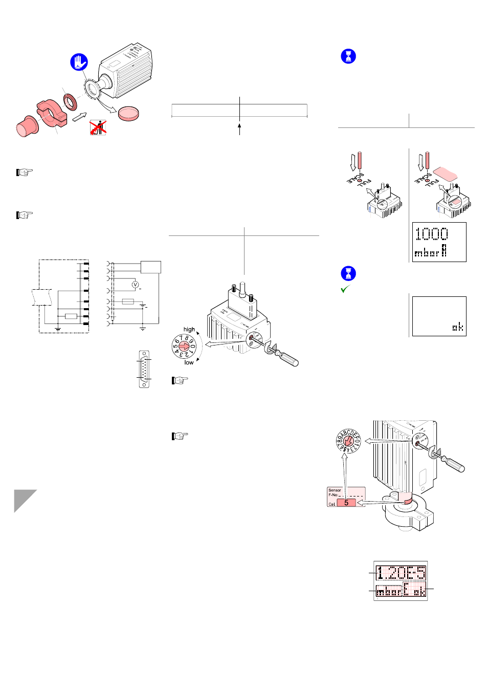
Adjusting the Gauge
(HPG400)
The adjustment of HPG400-SD and -SP (
→ [1]
and [2]) is slightly different from the procedure for
HPG400, which is described below.
The gauge is factory calibrated. If used under different cli-
matic conditions, at extreme temperatures, through aging or
contamination and after exchanging the sensor, the char-
acteristic curve can be offset and readjustment can become
necessary. Only the Pirani element can be adjusted and only
at atmosphere.
Readjustment becomes necessary if
• at atmosphere the output voltage is <9.75 V or the display
reading is • when venting the vacuum system, the output voltage reaches 9.75 V before the measured pressure has (For more details → [1], "Maintenance, Repair"). Adjustment of the Pirani part under high vacuum -3 mbar is reached for the first time. Adjustment of the Pirani part at atmospheric pressure: Put the gauge into operation. Operate the gauge for ≈10 minutes at atmos- pheric pressure. If the gauge was operated ≈30 minutes is to be expected (gauge temperature = environmental temperature). Adjust the gauge HPG400 without display 353-520 353-522 HPG400 with display 353-521 353-523 Insert a pin ( ≈ш1.3Ч50mm) through the opening for at least 5 seconds. — ≈10 s Automatic adjustment in progress. Adjustment completed. — Adjusting the Calibration Setting of the The sensor is factory calibrated. The calibration setting of the Display (HPG400 with part numbers 353-521 and 353-523) Pressure reading Pressure unit Status
reached atmosphere (Gauges with display will show the
error "5" at atmosphere (Pirani sensor warning)).
conditions:
The Pirani part is automatically adjusted by the hot cathode
part when the gauge is activated and the pressure range
1 … 3×10
within the hot cathode range, a cooling-down
time of
Hot Cathode Part
hot cathode range 0 … F is printed on the label. Correct this
value with the
the sensor. Before operating the gauge for the first time or
after replacing the sensor, check the calibration value setting
and adjust it if necessary.