INFICON HPG400 ATM to High-Vacuum Gauge User Manual
High pressure / pirani gauge, Safety, Technical data
High Pressure / Pirani Gauge
HPG400
HPG400-SD
HPG400-SP
Instruction Sheet
Incl. EC Declaration of Conformity
tima31e1-b (2011-10)
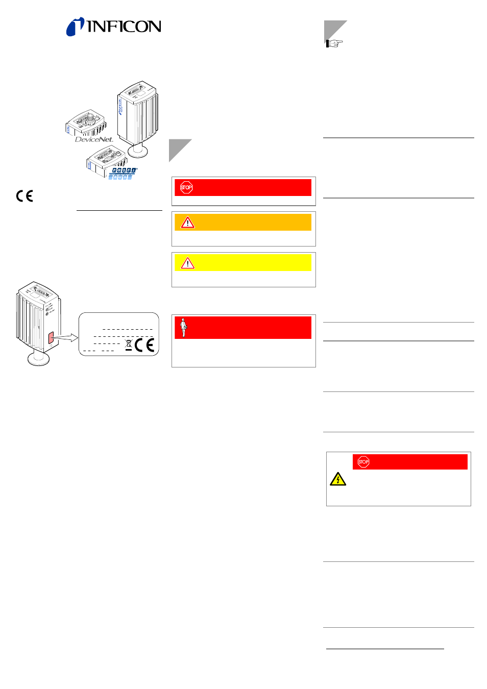
Product Identification
In all communications with INFICON, please specify the in-
formation on the product nameplate. For convenient refer-
ence copy that information into the space provided below.
Model:
PN:
SN:
V W
INFICON AG, LI-9496 Balzers
Validity
This document applies to products with part number:
HPG400 (
without display)
353-520
(DN 25 ISO-KF)
353-522
(DN 40 CF-R)
HPG400
(with display)
353-521
(DN 25 ISO-KF)
353-523
(DN 40 CF-R)
HPG400-SD
(with DeviceNet interface and switching functions)
353-527
(DN 25 ISO-KF)
353-528
(DN 40 CF-R)
HPG400-SP
(with Profibus interface and switching functions)
353-525
(DN 25 ISO-KF)
353-526
(DN 40 CF-R)
The part number (PN) can be taken from the product name-
plate.
If not indicated otherwise in the legends, the illustrations in
this document correspond to the gauge with part number
353-520. They apply to the other types of the HPG400 family
by analogy.
We reserve the right to make technical changes without prior
notice.
All dimensions in mm.
Intended Use
The High Pressure / Pirani Gauges of the type HPG400,
HPG400-SD and -SP gauges have been designed for vac-
uum measurement of gases and gas mixtures in a pressure
range of 2×10
-6
… 1 mbar. The control range of the gauge
allows trend display from <1 mbar to 1000 mbar.
They must not be used for measuring flammable or combus-
tible gases in mixtures containing oxidants (e.g. atmospheric
oxygen) within the explosion range.
The gauges can be operated in connection with the INFICON
Vacuum Gauge Controller VGC4xx or with other control de-
vices.
Functional Principle
Over the whole measuring range, the measuring signal is
output as logarithm of the pressure.
The HPG400 functions with a hot cathode ionization mano-
meter, which is controlled by the built-in Pirani manometer
(control range). The hot cathode is switched on only below
the changeover threshold of
≈1 mbar (to prevent filament
burn-out). For pressures above this threshold, the Pirani sig-
nal is output.
Trademark
DeviceNet™ Open DeviceNet Vendor Association, Inc.
Safety
Symbols Used
DANGER
Information on preventing any kind of physical injury.
WARNING
Information on preventing extensive equipment and
environmental damage.
Caution
Information on correct handling or use. Disregard can lead
to malfunctions or minor equipment damage.
Personnel Qualifications
Skilled personnel
All work described in this document may only be carried
out by persons who have suitable technical training and
the necessary experience or who have been instructed by
the end-user of the product.
General Safety Instructions
• Adhere to the applicable regulations and take the ne-
cessary precautions for the process media used.
Consider possible reactions with the product materials.
Consider possible reactions (e.g. explosion) of the
process media due to the heat generated by the product.
• Adhere to the applicable regulations and take the ne-
cessary precautions for all work you are going to do and
consider the safety instructions in this document.
• Before beginning to work, find out whether any vacuum
components are contaminated. Adhere to the relevant
regulations and take the necessary precautions when
handling contaminated parts.
Communicate the safety instructions to all other users.
Liability and Warranty
INFICON assumes no liability and the warranty becomes null
and void if the end-user or third parties
• disregard the information in this document
• use the product in a non-conforming manner
• make any kind of interventions (modifications, alterations
etc.) on the product
• use the product with accessories not listed in the corre-
sponding product documentation.
The end-user assumes the responsibility in conjunction with
the process media used.
Gauge failures due to contamination or wear and tear, as
well as expendable parts (e.g. filament), are not covered by
the warranty.
Technical Data
In some points, the technical data of HPG400-SD
and -SP differ from those of HPG400, which are
given below (
→ "Technical Data" in [1] and [2]).
Measuring range (air, N
2
)
Hot cathode
Pirani (control range)
2×10
-6
… 1 mbar
1×10
-2
… 1000 mbar
Accuracy
10
-5
… 1 mbar
±15% of reading, valid be-
tween 10
-5
mbar and
changeover threshold setting
(
↔ HP>)
Repeatability
10
-5
… 10
-1
mbar
10
-1
… 100 mbar
(after 10 min. stabilization)
±2% of reading
±30% of reading
Emission of hot cathode
Changeover
threshold
(selectable steps)
1 mbar, 5×10
–1
mbar,
2×10
–1
mbar, 1×10
–1
mbar,
5×10
–2
mbar (
↔ HP>)
Emission current
from 1
mbar
to 2×10
–6
mbar
rising continuously
4 µA
130 µA
Anode voltage
180 VDC
Output signal
(measuring signal)
Voltage
range
0 … +10.2 V
Measuring
range
Hot cathode
Pirani
1.5 … 7.5 V
8.5 … 9.75 V
Overrange hot cathode
Underrange hot cathode
7.5 V ≤ U ≤ 8 V
0.5 V ≤ U ≤ 1.5 V
Overrange
Pirani
Underrange Pirani
9.75 V ≤ U ≤ 10.2 V
8 V ≤ U ≤ 8.5 V
Relationship voltage-pressure
Hot cathode
Pirani
logarithmic
1 V/decade
0.25 V/decade
Error signal (
→ [1])
Hot cathode
Pirani
≈0.3 V
≈0.5 V
Minimum load impedance
10 k
Ω, short-circuit proof
Gauge identification
56 k
Ω between Pin 10 and
Pin 5 (sensor cable)
RS232C interface
Data rate
Data format
→ "Power Connection"
9600 baud
binary
8 data bits
one stop bit, no parity bit
no handshake
Further information on the RS232C interface
→ [1]
Display panel
(353-521, 353-523)
Dimensions
Pressure units
LCD matrix, 32×16 pixels
with background illumination
16.0 mm × 11.2 mm
mbar (default), Torr, Pa
Selecting the pressure unit
→ [1]
Supply
DANGER
The gauge must only be connected to power
supplies, instruments or control devices that
conform to the requirements of a grounded pro-
tective extra-low voltage (SELV). The connection
to the gauge has to be fused
1)
.
Voltage at gauge
24 VDC (20 … 28 VDC)
ripple ≤2 V
pp
)
2)
Current consumption
Standard
Emission start (200 ms)
≤0.5 A
≤1.4 A
Fuse required
1)
1.25
AT
Power consumption
≤16 W (HPG400)
Electrical connection
D-Sub 15-pin, male
Sensor cable
For analog values only
For all functions
4 conductors, shielded
7 conductors, shielded
Cable length (24 VDC)
≤35 m (0.25 mm²/conductor)
≤50 m (0.34 mm²/conductor)
≤100 m (1.0 mm²/conductor)
For operation with RS232
(e.g. VGC4xx)
≤30 m
1)
INFICON gauge controllers fulfill these requirements.
2)
Consider the voltage drop in the supply lines.