Operation, Deinstallation, Power connection (bcg450) – INFICON BCG450 ATM to Ultra-High Vacuum Triple Gauge User Manual
Page 3: Gas type dependence, Adjusting the gauge, Display
Caution
Caution: vacuum component
Dirt and damages impair the function of the
vacuum component.
When handling vacuum components, take ap-
propriate measures to ensure cleanliness and
prevent damages.
Caution
Caution: dirt sensitive area
Touching the product or parts thereof with bare
hands increases the desorption rate.
Always wear clean, lint-free gloves and use
clean tools when working in this area.
The gauge may be mounted in any orientation. To
keep condensates and particles from getting into the
measuring chamber, preferably choose a horizontal
to upright position.
The gauge is supplied with a built-in grid. For poten-
tially contaminating applications and to protect the
electrodes against light and fast particles, installa-
tion of
• the optional baffle or
• the optional centering ring with baffle
is recommended (
→ [1]).
Remove the protective lid and install the product to the
vacuum system.
We recommend to install the gauge without applying
vacuum grease.
Protective lid
Clamp
Seal with centering ring
Keep the protective lid.
Power Connection
(BCG450)
The following information on the electrical con-
nection as well as the wiring diagram applies to
BCG450 only (
→ [1] and [2] for details on the
electrical connection and additional functions of
BCG450-SD and -SP).
Make sure the vacuum connection is properly made
(
→ "Vacuum Connection").
n
If no connection cable is available, make one according
to the following diagram.
TxD
RxD
Degas
42 k
Ω
13
14
7
8
2
12
5
15
1.25 AT
24V
Degas
Ident.
RS232
10
-
-
-
+
-
Measuring
signal
1
4
8
9
1
15
D-Sub,15-pin,
female,
soldering side
Atmospheric pres-
sure reached 1)
Common (power GND 24V supply)
Ground (housing, vacuum connection)
Electrical connection
Pin 1
Relay "Atmosphere
reached", n. o. contact
1)
Pin 2
Measuring signal output
0 … +10.13 V
Pin 4
Relay "Atmosphere
reached", com contact
1)
Pin 5
Supply common
0 V
Pin 7
Degas on, active high
0 V/+24 V
Pin 8
Supply
+24 V
Pin 10
Gauge identification
Pin 12
Measuring signal common
Pin 13
RS232, TxD
Pin 14
RS232, RxD
Pin 15
Do not connect
Pins , 3, 6, 9 and 11 are not connected internally.
1)
Detailled information on the atmosphere switching
function and the "Atmosphere reached" relay
→ [1].
o
Connect the sensor cable to the gauge.
p
Secure the cable connector with the lock screws.
q
Connect the sensor cable to the controller.
Operation
When the supply voltage is applied, the measuring signal is
available between pins 2 (+) and 12 (–) (Relationship Meas-
uring Signal – Pressure
→ "Technical Data" and [1]).
BCG450-SD and -SP can also be operated via the corre-
sponding fieldbus interface (DeviceNet or Profibus,
→ [1]
and [2] for further details and functions).
Allow for a stabilizing time of
≈10 minutes. Once the gauge
has been switched on, permanently leave it on irrespective of
the pressure.
Gas Type Dependence
Pressure range
Measuring
principle
Gas type
dependence
10 … 1500 mbar
capacitance
diaphragm
sensor
independent of gas
type, no correction
required
1 … 10 mbar
capacitance
diaphragm
sensor and
Pirani sensor
crossover range
2×10
-2
… 1 mbar
Pirani sensor
1)
5Ч10
-3
…
2Ч10
-2
mbar
Pirani sensor
and
hot cathode
ionisation
sensor (BA)
crossover range
5Ч10
-10
…
5Ч10
-3
mbar
hot cathode
ionisation
sensor (BA)
1)
1)
→ Table "Technical Data, Calibration factors"
Adjusting the Gauge
The gauge is adjusted automatically (adjustment of the
atmosphere switching function (atmosphere sensor)
→ [1]).
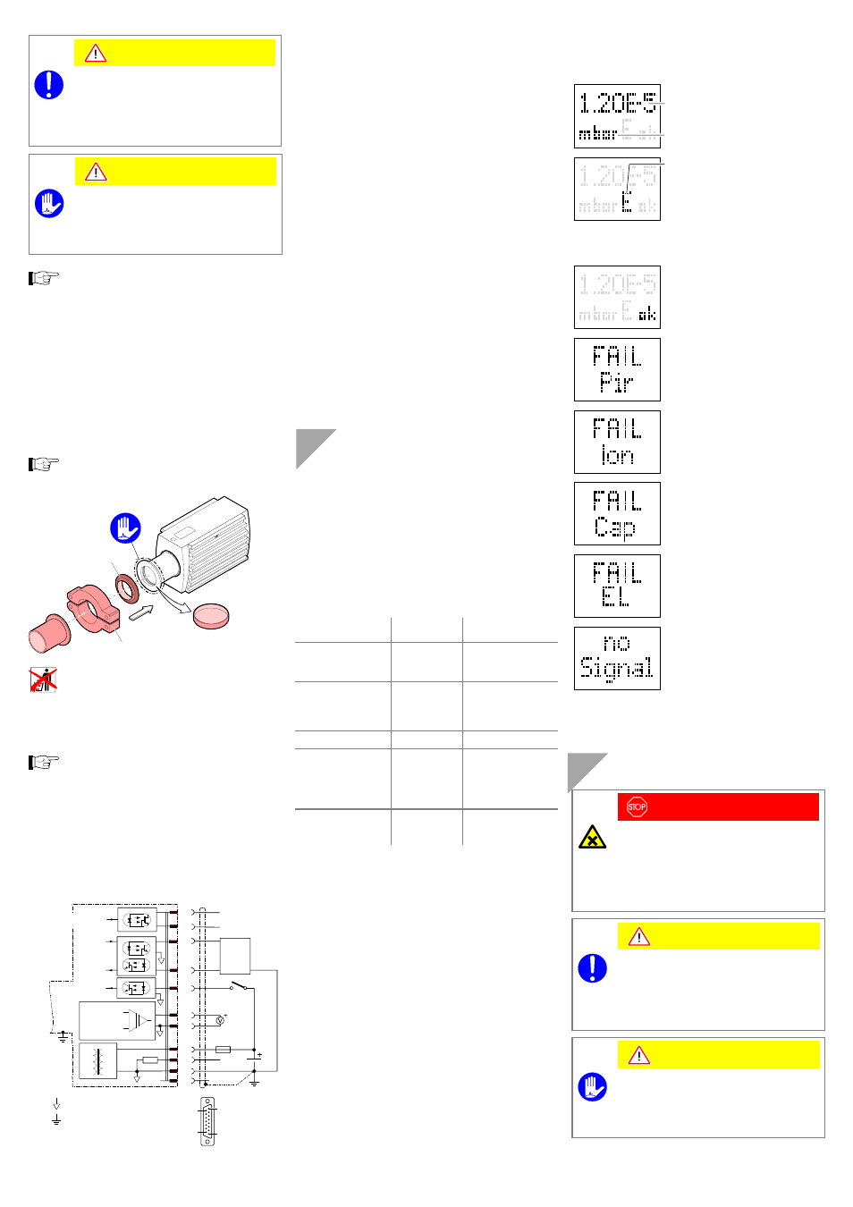
Display
(BCG450 with part numbers 353-552 and 353-553)
Pressure reading
Pressure unit
Function display
(none) Pirani operation
E
Emission 25
μA
E
.
Emission 5 mA
D
Degas
Error display:
No error
(green background illumination)
Pirani sensor error
(red background illumination)
BA sensor error
(red background illumination)
Diaphragm sensor error
(red background illumination)
EEPROM error
(red background illumination)
Internal data connection failure
(red background illumination)
Deinstallation
DANGER
DANGER: contaminated parts
Contaminated parts can be detrimental to health
and environment.
Before beginning to work, find out whether any
parts are contaminated. Adhere to the relevant
regulations and take the necessary precautions
when handling contaminated parts.
Caution
Caution: vacuum component
Dirt and damages impair the function of the vac-
uum component.
When handling vacuum components, take ap-
propriate measures to ensure cleanliness and
prevent damages.
Caution
Caution: dirt sensitive area
Touching the product or parts thereof with bare
hands increases the desorption rate.
Always wear clean, lint-free gloves and use
clean tools when working in this area.