Installation, Measuring signal vs. pressure, Gas type dependence – INFICON BCG450 ATM to Ultra-High Vacuum Triple Gauge User Manual
Page 2: Vacuum connection, P = 10, C × pressure indicated
Atmosphere switching
function (relay "Atmosphere
reached")
BCG450
BCG450-SD/-SP
Atmospheric pressure
threshold programmable via
serial interfaces (
→ [1])
threshold value programma-
ble via RS232 (default value
99%)
threshold value programma-
ble via fieldbus interfaces
(
→ corresponding communi-
cation protocols).
RS232C interface (BCG450)
Data rate
Data format
Connector
9600 Baud
binary
8 data bits
one stop bit
no parity bit
no handshake
→ "Power Connection"
Further information on the RS232C interface
→ [1]
Display (353-552, 353-553)
LCD matrix, 32×16 pixels
Background illumination
two colors red/green
Dimensions
16.0 mm × 11.2 mm
Pressure units
mbar (default), Torr, Pa
(Selecting the pressure unit
→ [1])
Supply
DANGER
The gauge must only be connected to power
supplies, instruments or control devices that
conform to the requirements of a grounded pro-
tective extra-low voltage (SELV). The connection
to the gauge has to be fused
1)
.
Voltage at gauge
+24 VDC (+20 … +28 VDC)
(ripple
≤2 V
pp
)
2)
Power consumption
Standard
Degas
Emissions start (200 ms)
≤0.5 A
≤0.9 A
≤1.4 A
Fuse required
1)
1.25
AT
Power consumption
≤18 W (BPG450)
Electrical connection
D-Sub, 15-pin, male
Sensor cable
shielded, number of con-
ductors depending on the
functions used (max.
15 conductors plus shield-
ing).
Cable length (24 VDC
(conductor cross-section)
≤35 m (0.25 mm²)
≤50 m (0.34 mm²)
≤100 m (1.0 mm²)
For operation with
RS232C interface
≤30 m
Materials on the vacuum side
Housing, supports,
screens
Feedthroughs
Insulator
Cathode
Cathode holder
Pirani element
Diaphragm
Sensor electrodes
stainless steel
NiFe nickel plated
glass
iridium, yttrium oxide (Y
2
O
3
)
molybdenum
tungsten, copper
ceramic (Al
2
O
3
)
SnAg
Internal volume
DN 25 ISO-KF
DN 40 CF-R
≈24 cm
3
≈34 cm
3
Maximum admissable
pressure
5 bar (absolute)
Admissible temperatures
Storage
Operation
Bakeout
–20 … +70 °C
0 … +50 °C
+80 °C (at vacuum connec-
tion, without electronics unit,
horizontally mounted)
Relative humidity
Year’s mean
During 60 days
≤65% (not condensable)
≤85% (not condensable)
Use indoors
only
altitude up to 2000 m NN
Mounting orientation
any
Type of protection
IP 30
1)
INFICON gauge controllers fulfill these requirements.
2)
Measured at the sensor cable connector (consider the voltage
drop on the sensor cable).
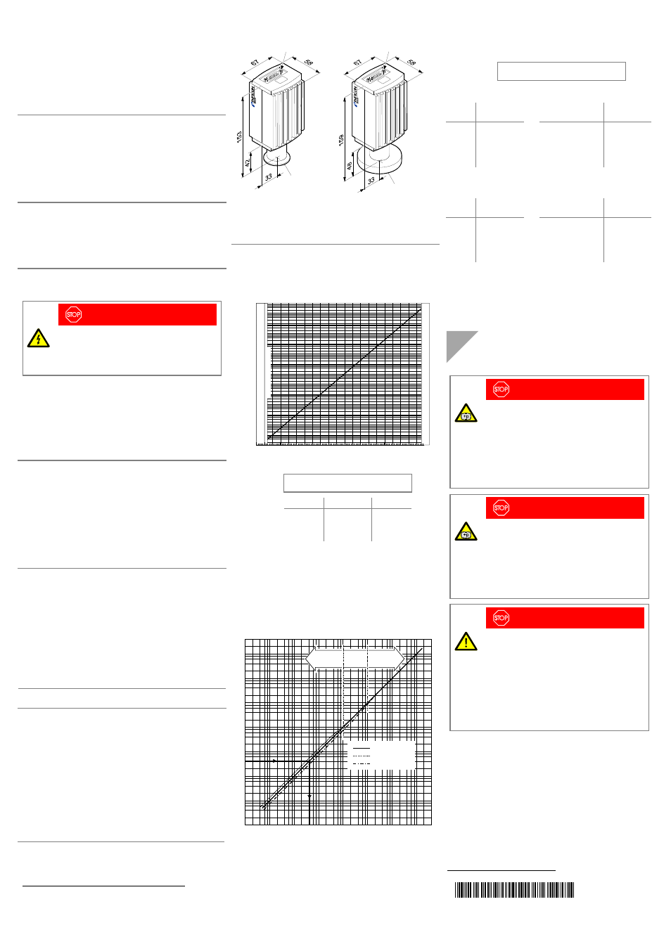
Dimensions [mm]
DN 25 ISO-KF
DN 40 CF-R
4-40UNC 2B
4-40UNC 2B
Weight
353-550 / -552 / -561
353-551 / -553
353-554 / -557 / -562
353-556 / -558
≈305 g
≈565 g
≈445 g
≈710 g
Measuring Signal vs. Pressure
1E+01
1E–01
1E–03
1E–05
1E–07
1E–09
1E+03
Measuring signal U[V]
0.0
1E+04
1E+02
1E+00
1E–02
1E–04
1E–06
1E–08
1E–10
1.0
2.0
3.0
4.0
5.0
6.0
7.0
8.0
9.0
10.0
Pressure p [mbar]
In
a
dmis
sib
le
ran
ge
S
ens
or
er
ro
r
In
ad
m
is
sible ra
ng
e
p = 10
(U-7.75)/0.75+c
U p c
[V] [mbar] 0
[V] [Pa] 2
[V] [Torr]
-0.125
where p pressure
U measuring
signal
c
constant (pressure unit dependent)
Gas Type Dependence
Indicated pressure (gauge calibrated for air)
10
2
8
6
4
2
10
1
8
6
4
2
10
0
8
6
4
2
10
–1
8
6
4
2
10
–2
8
6
4
2
10
–3
10
–4
2
4 6
10
–3
2
4 6
10
–2
2
4 6
2
4 6
10
0
2
4 6
10
1
10
–1
10
–4
p
eff
[mbar]
2
4 6
10
2
2
4 6
10
3
8
6
4
2
10
3
p [mbar]
8
6
4
2
4
2
2
Air, O
2
, CO, N
2
He
Ar
Pirani
sensor
Cross-
over
range
Capacitance
diaphragm
sensor
Calibration factors
(Gauge calibrated for air)
p
eff
= C × pressure indicated
Valid for Pirani pressure range 2×10
-2
… 1 mbar:
Gas
type
Calibration
factor C
Gas
type Calibration
factor C
He
Ne
Ar
Kr
Xe
0.8
1.4
1.7
2.4
3.0
H
2
air, O
2
, CO, N
2
CO
2
H
2
O vapor
freon 12
0.5
1.0
0.9
0.5
0.7
Valid for BA pressure range
≤5×10
-3
mbar:
Gas
type
Calibration
factor C
Gas
type Calibration
factor C
He
Ne
Ar
Kr
Xe
5.9
4.1
0.8
0.5
0.4
H
2
air, O
2
, CO, N
2
2.4
1.0
(Indicated factors are average values.)
Installation
Vacuum Connection
DANGER
DANGER: overpressure in the vacuum system
>1 bar
Injury caused by released parts and harm
caused by escaping process gases can result if
clamps are opened while the vacuum system is
pressurized.
Do not open any clamps while the vacuum sys-
tem is pressurized. Use the type clamps which
are suited to overpressure.
DANGER
DANGER: overpressure in the vacuum system
>2.5 bar
KF flange connections with elastomer seals (e.g.
O-rings) cannot withstand such pressures.
Process media can thus leak and possibly
damage your health.
Use O-rings provided with an outer centering
ring.
DANGER
DANGER: protective ground
Incorrectly grounded products can be extremely
hazardous in the event of a fault.
The gauge must be electrically connected to the
grounded vacuum chamber. This connection
must conform to the requirements of a protective
connection according to EN 61010:
• CF connection fulfill this requirement
• For gauges with a KF flange, use a conduc-
tive metallic clamping ring
t i ma 4 0 e 1 - b
(2011-04)
Original: German tima40d1-b (2011-04)