Igure, Apacitance, Djustments – INFICON PLO-10i Phase Lock Oscillator User Manual
Page 28
PLO-10 PHASE LOCK OSCILLATOR
CALCULATING CRYSTAL POWER
4-2
If you are using a crystal holder and cable supplied with your PLO-10 then you should
not have to change the course adjustment. Connect the cable and crystal holder to the
PLO but don’t install a crystal.
If the Sweep LED is flashing, press and hold the Reset button and then turn the fine
trimmer counter clockwise until it just stops flashing. Go back and forth a few times to
get a feel for the point where the Sweep LED just stops flashing. Release the Reset
button and the Sweep LED should begin to flash again.
Install a crystal. The PLO should lock. Even so, press and hold the Reset button and
again adjust the fine trimmer to the point where the flashing just stops. The capacitance
cancellation adjustment is now perfect. Remember to check this adjustment whenever
the crystal holder is moved or changed to a new environment.
If you could not find the proper zero capacitance point using the fine trimmer alone, then
we have found the following approach which is best for adjusting the coarse trimmer.
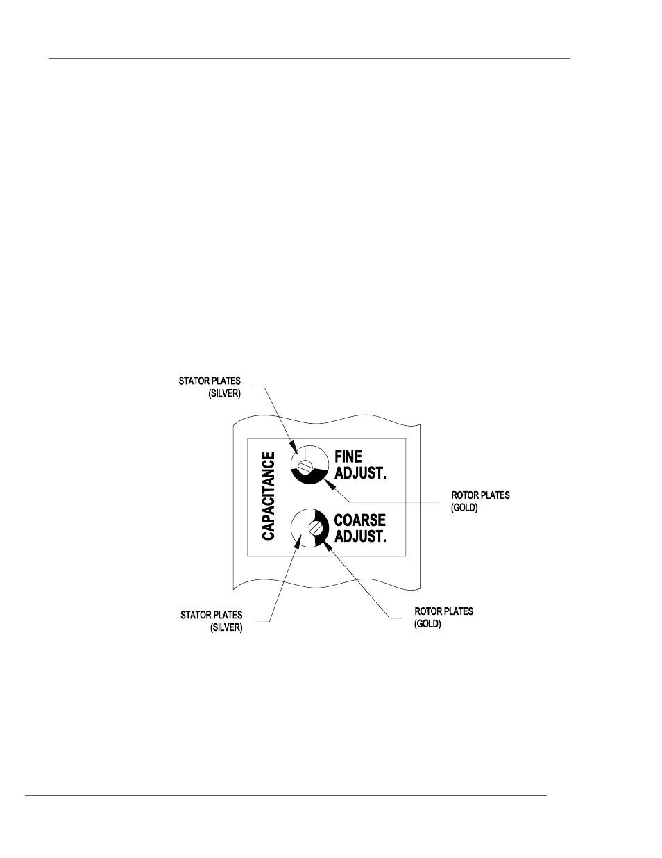
First adjust the fine trimmer so that it is 50% meshed and the rotor plates are below the
shaft with the oscillator upright. You can see these plates through the oversize
adjustment hole. See Figure 6. Next connect a cable and crystal holder, if you haven’t
already done so. Don’t install the crystal at this point.
Figure 6 Capacitance Adjustments
Do not press the reset button, now slowly turn the course trimmer clockwise while
watching the Lock and Unlock LED’s. The green, Lock, LED will come on when the
capacitance is grossly out of adjustment. Continue turning the course trimmer clockwise
until the Unlock LED comes on. The adjustment is getting close. Press and hold the
reset button, Slowly continue to turn the trimmer clockwise until the yellow, Sweep, LED
begins to flash. If you continue to turn clockwise the Sweep LED will cease flashing, but