Superlogic 2500 manual – Hydro-Logic SuperLogic 2500 User Manual
Page 10
370 Encinal Street, Suite 150, Santa Cruz, CA 95060
(888) 426-5644, Fax (831) 336-9840
www.hydrologicsystems.com
SuperLogic 2500 Manual
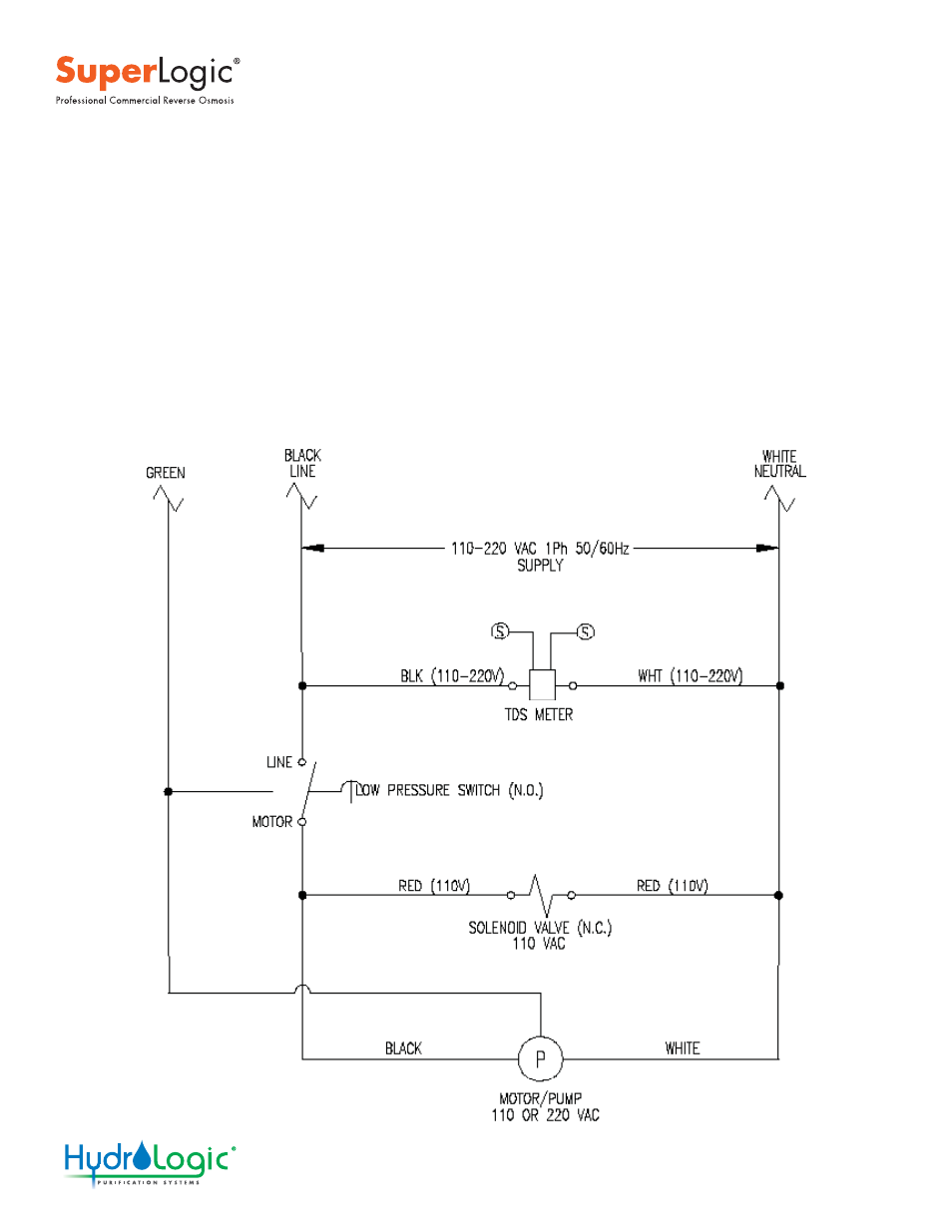
Electrical
(Figure 2 - Electrical Diagram)
WARNING! THE SYSTEM CAN START AT ANY TIME WHEN POWER IS CONNECTED. DO NOT CONNECT POWER UNTIL THE SYSTEM IS
COMPLETELY INSTALLED AND READY TO RUN.
The SuperLogic 2500 system is built with a standard 115v three-prong plug. Be sure the receptacle you use is on a circuit that
has a Ground Fault Interrupter (GFCI) and has suffi
cient capacity for the opera ng current as listed in the system specifi ca ons. It is
recommended that the system be installed on a dedicated circuit to prevent overloading on system start-up.
Op onal External Float Switch Wiring (For non-pressurized tanks only)
A piggy-back connector is supplied with the system. Please see addi onal installa on informa on included with the fl oat switch.
Figure 2 - Electrical Diagram