Operational test procedure, Maintenance, Trouble shooting – Hydrolevel 1100 User Manual
Page 4: Dimensions specifications
LIMITED MANUFACTURERʼS WARRANTY
We warrant products manufactured by Hydrolevel Company to
be free from defects in material and workmanship for a period
of two years from the date of manufacture or one year from
the date of installation, whichever occurs first. In the event of
any claim under this warranty or otherwise with respect to our
products which is made within such period, we will, at our
option, repair or replace such products or refund the purchase
price paid to us by you for such products. In no event shall
Hydrolevel Company be liable for any other loss or damage,
whether direct, indirect, incidental or consequential. This war-
ranty is your EXCLUSIVE remedy and shall be IN PLACE OF
any other warranty or guarantee, express or implied, includ-
ing, without limitation, any warranty of MERCHANTABILITY or
fitness for a particular purpose. This warranty may not be
assigned or transferred and any unauthorized transfer or
assignment thereof shall be void and of no force or effect.
83 Water Street • New Haven, CT 06511 • Phone (203) 776-0473 • FAX (203) 773-1019 •
www.hydrolevel.com
OPERATIONAL TEST PROCEDURE
IMPORTANT: Do not run boiler unattended until the following procedure is completed
1. Before raising the water level above the Model 1100, turn on power to the boiler and set the thermostat to call for heat. Both the green
“POWER” LED and amber “LOW WATER” LED should illuminate. The burner should not fire. IMPORTANT: If the burner fires with no water
at the probe, immediately shut down power to the boiler and refer to the Trouble Shooting instructions below.
2. Proceed to fill the boiler with water. When water reaches the LWCO position, the burner should fire. If the burner does not fire, refer to the
Trouble Shooting instructions below.
3. Turn off the power to the boiler and finish filling the system.
4. Before leaving the job, power up the system and push the TEST button on the Model 1100 to simulate a low water condition. The amber
“LOW WATER” LED should illuminate and the burner should shut down.
MAINTENANCE
EVERY YEAR
Check control operation annually by pressing the TEST button. The amber “LOW WATER” LED should illuminate and the
burner should shut down.
5 YEARS
Remove the low water cut-off every five years and clean all surfaces in contact with water.
TROUBLE SHOOTING
IF THE BURNER DOES NOT SHUT DOWN
(when water is below the probe or
when the TEST button is pressed)
1. Turn off boiler power immediately and re-check wiring.
2. Turn off boiler power and drain system. Remove low water cut-
off and check for adequate clearance – no metal should be in
contact with the control’s metal probe tip.
IF THE BURNER DOES NOT FIRE
1. Make sure water has reached the level of the control.
2. Check green wire for proper ground. Make sure the wire is
attached to an unpainted surface that is electrically common to
the boiler.
3. Check to ensure the control’s metal probe tip is not surrounded
by an air pocket. Shut down power to the boiler and slowly
loosen, but do not remove, the control. Allow any air to escape.
When water begins to seep past threads, retighten the control.
4. Re-check wiring and check for correct incoming voltage.
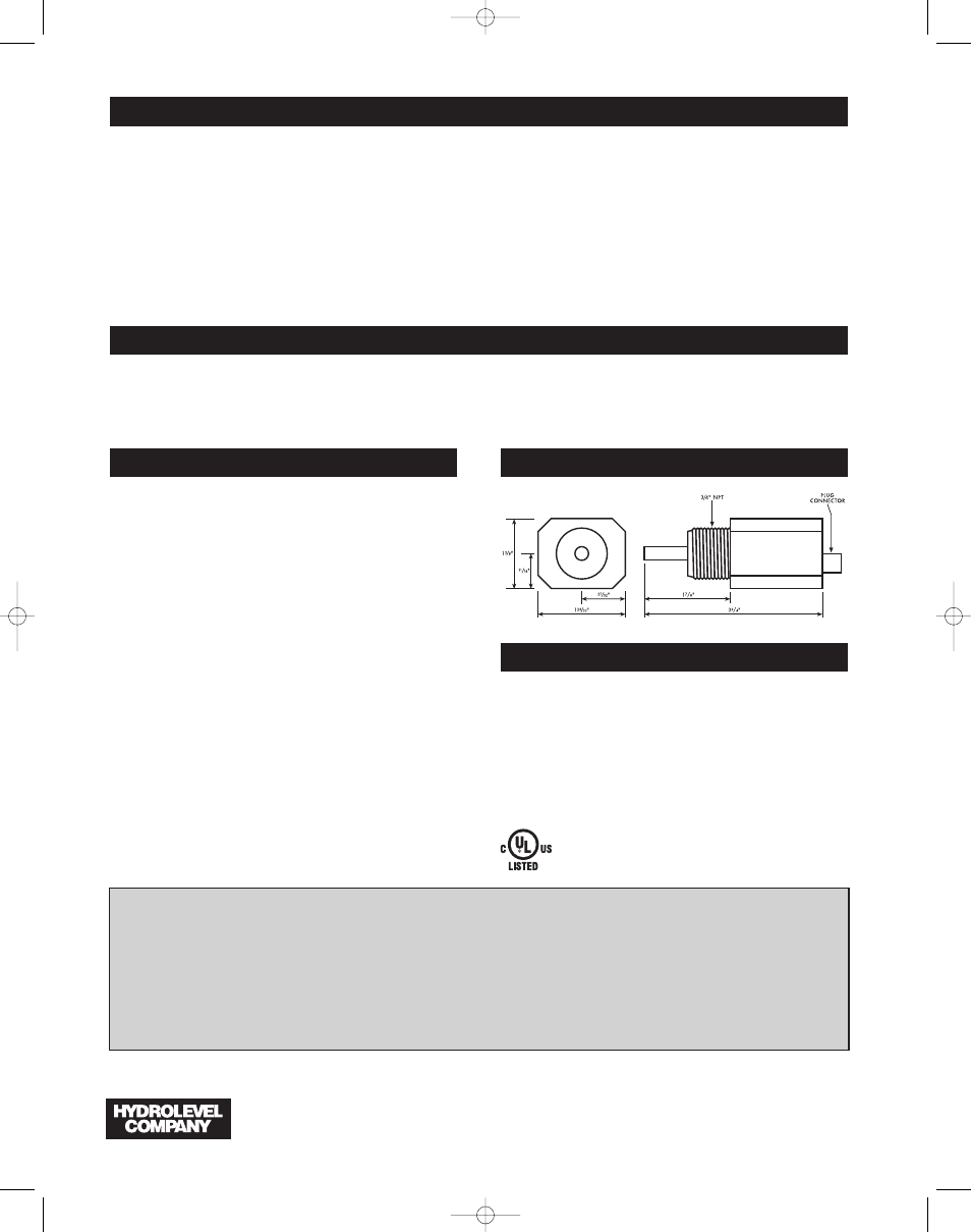
DIMENSIONS
SPECIFICATIONS
VOLTAGE
24 VAC
POWER CONSUMPTION
1 VA
SWITCHING CAPACITY
50 VA
MAX LOAD
5 Amps
MAX PRESSURE
160 PSI (11.25 kg/cm
2
)
MAX WATER TEMPERATURE
250°F (121°C)
MAX AMBIENT TEMPERATURE 170°F (77°C)
1100-0512
Model 1100 Instructions: Model 1100 Instructions 4/30/12 10:24 AM Page 4