Hmg 3010, 5 can functions – HYDAC HMG 3010 User Manual
Page 74
HMG 3010
Page 74
Edition 11/2011 - V04 R01
Part No.: 669855
6.5 CAN Functions
The HMG 3010 can be connected to a CAN bus system in conjunction with the CAN adapter
ZBE 3010. In this operating mode, the following functions are available in the HMG.
• Read-out of up to 32 measured values from predefined CAN messages
• Parameterisation and configuration of HYDAC CAN sensors
6.5.1 Electrical connections
When connecting the HMG 3010 and the ZBE 3010 to a CAN bus system the following
safety information must be adhered to:
CAUTION!
- The CAN adapter ZBE 3010 is absolutely essential when connecting to a CAN bus sys-
tem.
- The CAN adapter ZBE 3010 must be connected to jack D/H on the HMG 3010 using the
5-pole M12x1 connector cable! If connected to a different input jack, an error message
will be displayed..
- The CAN adapter ZBE 3010 must only be connected directly, i.e. not using a Y-adapter,
to jack D/H on the HMG 3010!
- The HMG 3010 may only be connected to a CAN bus system via the CAN-Adapter ZBE
3010; either via the M12x1 male connector or via the SUB-D male connector (both con-
nectors must not be used at the same time)!
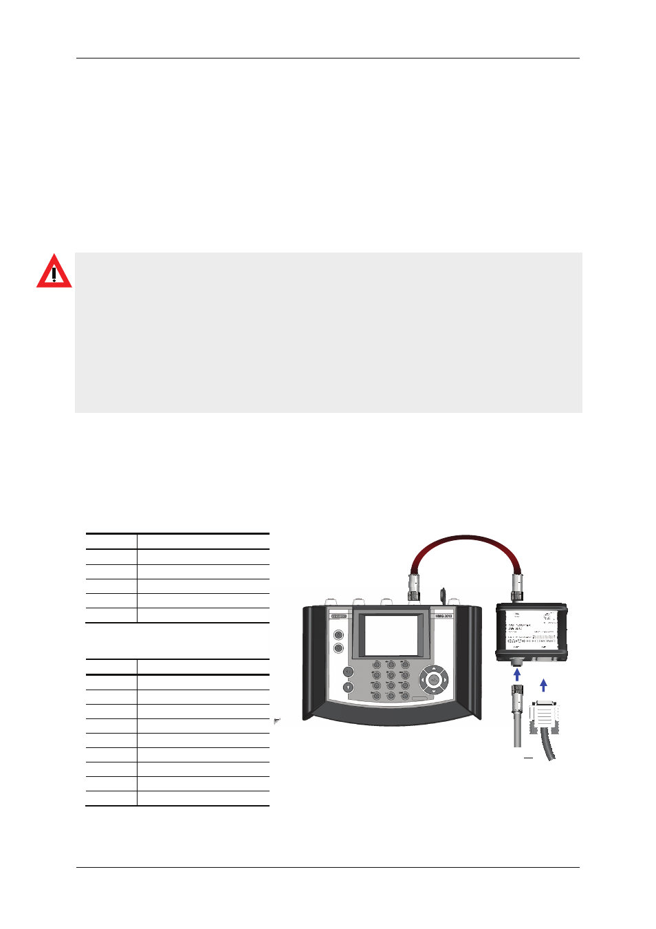
6.5.1.1 CAN connection to the ZBE 3010
The CAN bus system can be connected electrically either by the 5-pole male connection or
the 9-pole SUB-D male connection.
Only one bus system may be connected to one of the two connections!
• Pin assignment for M12x1
Pin Signal
1 n.c.
2 +12
V
3 GND
4 CAN
HIGH
5 CAN
LOW
• Pin assignment for Sub-D
Pin Signal
1 n.c.
2 CAN
LOW
3 GND
4 n.c.
5 n.c.
6 n.c.
7 CAN
HIGH
8 n.c.
9 +12V
Connection:
M12x1
or
Sub-D