HYDAC HMG 3010 User Manual
Page 25
HMG 3010
Page 25
Edition 11/2011 - V04 R01
Part No.: 669855
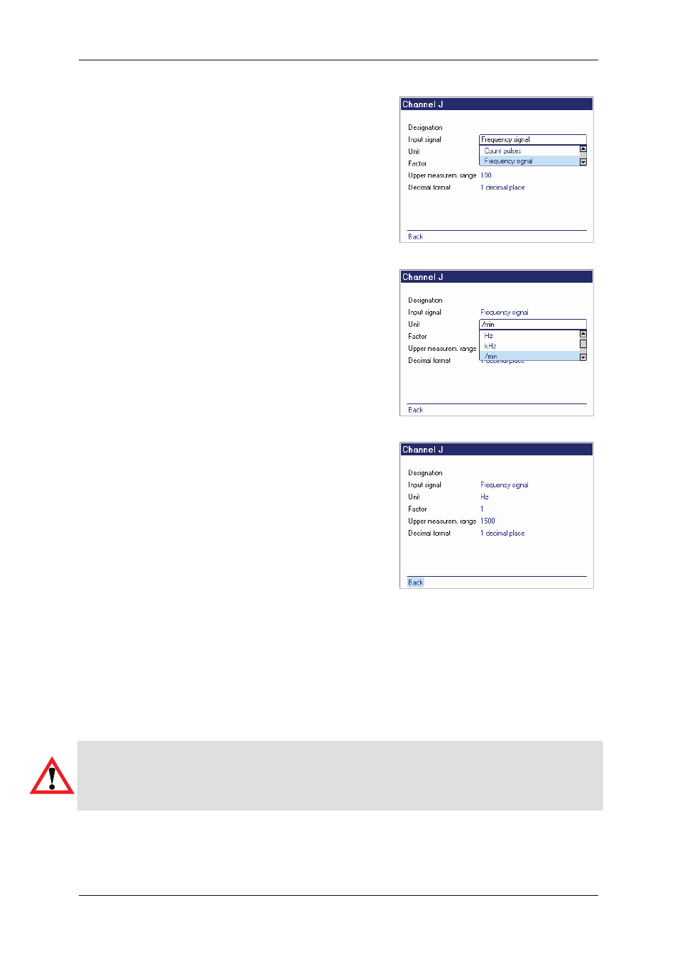
Input channels I and J are for digital (not
analogue) signals. As the input signal you
can choose between Count pulses and
Frequency signal. There are many possi-
bilities for this, e.g. speed sensors, proximity
switches, pulse generators, flow rate meas-
uring instruments with a frequency signal,
HYDAC HDS 1000, to name only a few. As
in the case of the analogue sensor inputs,
settings can be manually entered for the
input signal, unit of measurement and deci-
mal format.
In addition to these settings, a factor has
to be entered which is required for con-
version to the desired unit of measure-
ment.
Another special feature is that the Upper
measurem. range must be input. Frequen-
cies of up to 30000 Hz can be measured on
channels I and J, consequently a scale from
0 to 30000 is possible in the graphical dis-
play. If, for example, you record a speed of
up to 1450 rpm, an awkward Y-axis scale will
result in the graph. If you enter "1500" as the
Upper measurement range for this speed
measurement, for example, the Y-axis in the
graph will be scaled from 0 to 1500 rpm.
In this case the reason for inputting the upper measurement range is just a means of limiting
the scale of the Y-axis in the graphical display. You should set this value as close as possible
to that of the expected measured value in order to get the best possible graphical display.
If there are measured values higher than the upper measurement range, these are not lost.
The scale of the Y-axis can be changed again in the graph at any time later on.
Caution!
The measurement range of the frequency entries is 1 Hz to 30000 Hz. If, for example, the
rpm of a motor is recorded and this motor stops abruptly, the last rpm can still show in the
display for up to 2 seconds, depending on the measurement system, before 0 is displayed.