Multi-deck rotary switches, Choices and limitations: series 71 – Grayhill Multi-Deck Rotary Switches 71 Series User Manual
Page 13
Grayhill, Inc. • 561 Hillgrove Avenue • LaGrange, Illinois 60525-5997 • USA • Phone: 708-354-1040 • Fax: 708-354-2820 • www.grayhill.com
Rotary Switches
Multi-Deck Rotary Switches
Multi-Deck Rotary Switches
01 thru 12
1
02 thru 12
3
N or S
01 thru 08
2
02 thru 06
N or S
01 thru 05
3
02 thru 04
N or S
01 thru 04
4
02 or 03
N or S
01 thru 03
5
5
02
N or S
01 or 02
6
5
02
N or S
01 thru 12
1
02 thru 10
3
N or S
01 thru 08
2
02 thru 05
N or S
01 thru 12
1
02 thru 12
3
N or S
01 thru 08
2
02 thru 06
N or S
01 thru 12
1
02 thru 10
3
N or S
01 thru 08
2
02 thru 05
N or S
01 thru 05
1
02 thru 10
3
N or S
01 thru 05
2
02 thru 05
N or S
01 thru 05
4
1
02 thru 12
3
N or S
01 thru 05
4
2
02 thru 06
N or S
01 thru 05
4
3
02 thru 04
N or S
01 thru 04
4
4
02 or 03
N or S
01 thru 02
4
6
02
N or S
01 thru 05
4
1
02 thru 10
3
N or S
01 thru 05
4
2
02 thru 05
N or S
01 thru 04
2,4
1
02 thru 12
3
N or S
01 thru 04
2,4
2
02 thru 06
N or S
01 thru 04
2,4
1
02 thru 10
3
N or S
01 thru 04
2,4
2
02 thru 05
N or S
01 thru 03
1
02 thru 12
3
N or S
01 thru 03
2
02 thru 06
N or S
01 or 02
3
02 thru 04
N or S
01
4
02 or 03
N or S
01
5
02
N or S
01
6
02
N or S
01 thru 03
1
02 thru 10
3
N or S
01 thru 03
2
02 thru 05
N or S
01 thru 03
1
02 thru 12
3
N or S
01 thru 03
2
02 thru 06
N or S
01 thru 03
1
02 thru 10
3
N or S
01 thru 03
2
02 thru 05
N or S
30°
36°
30°
36°
36°
30°
36°
30°
36°
30°
36°
30°
36°
A
AS
AD
B
BS
BD
E
ES
ED
AF
ASF
ADF
BF
BSF
BDF
EF
ESF
EDF
BT
——
——
MA
MAS
——
MB
MBS
——
MAF
MASF
——
MBF
MBSF
——
C
——
——
CF
——
——
A =
1
/
8
" Diameter Shaft
B =
1
/
4
" Diameter Shaft
E = Metric Mount Shaft & Bushing
D = Adjustable Stops (Adj. Stop)
S = Shaft and Panel Seal (S/P Seal)
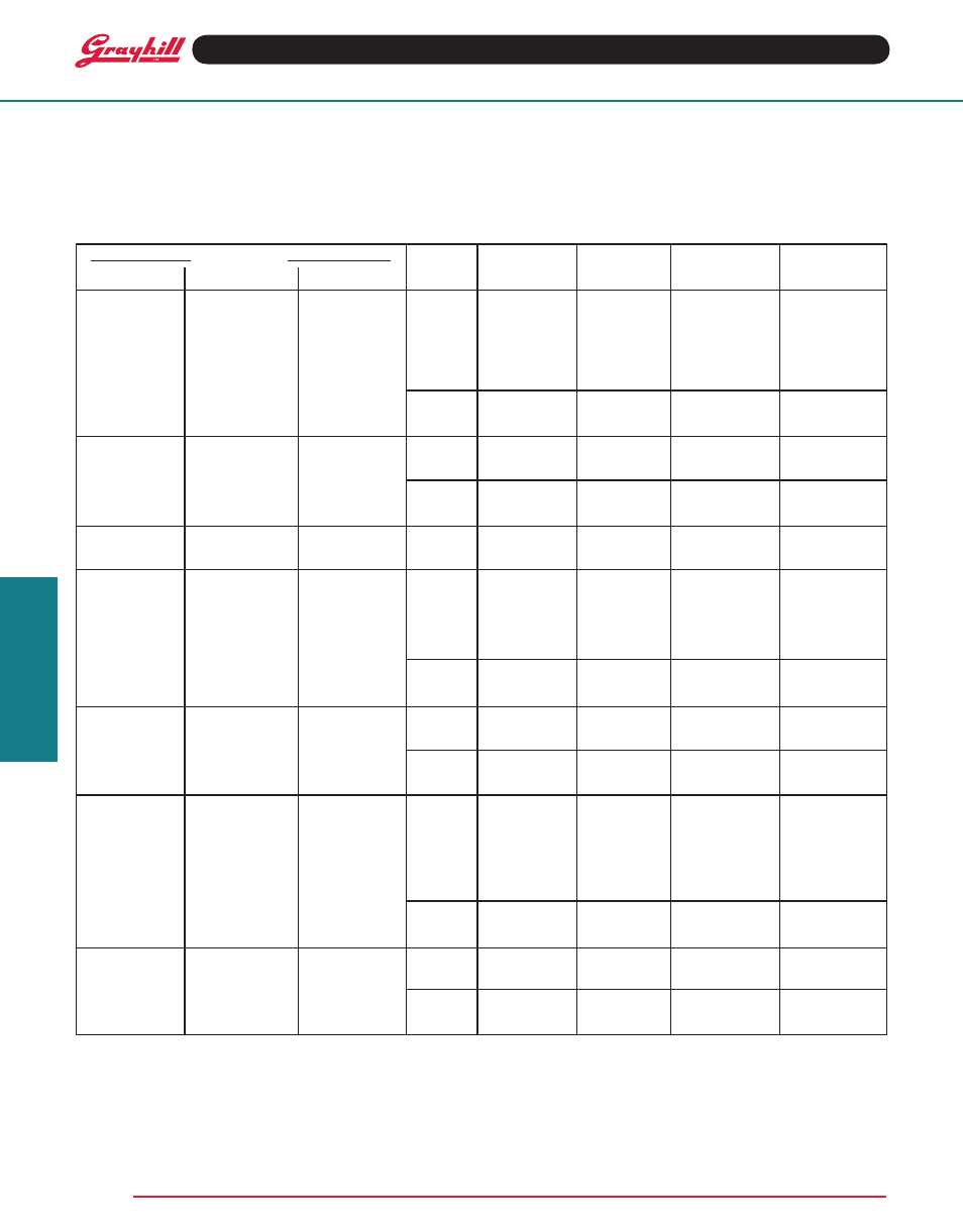
Style Choices
Angle of
No. Of
Poles
Positions
Shorting Or
Basic Style With S/P Seal Adj. Stop
throw
Decks
Per Deck
Per Pole
1
Non-Shorting
CHOICES AND LIMItAtIONS: Series 71
F = PC Mount Terminals
T = PC Mount Terminals and Process Sealed
Switching Decks & Bushing; no panel seal
M = Military
All switches without F or T have solder
lugs
C = Concentric Shaft
2 Switches with same Style and Angle of
Throw, one behind the other.
Limits below apply to either switch section
(A or B).
1
For Adjustable Stop styles (with the letter D),
use AJ instead of number of positions when
ordering.
2
Military Qualified PC mount switches of 3 or
4 operative decks have an additional spacer
deck after deck 2. Use total decks to calculate
length; but use only the number of operative
decks when creating the part number.
3
For 1-pole switches with maximum positions,
specify
Fixed stop after last position or
Continuous rotation when ordering. (Note: 1 p,
71BT, 10 positions, is available only as
Continuous).
4
In addition to qualified types (Solder lug–5
decks; PC mount–4 decks), Grayhill can pro-
vide switches with additional decks in the
materials of the ‘M’ style. Contact Grayhill.
5
Switches in 30° throw with 5 or 6 poles per deck
are not available with adjustable stops.