Grayhill Multi-Deck Rotary Switches 71 Series User Manual
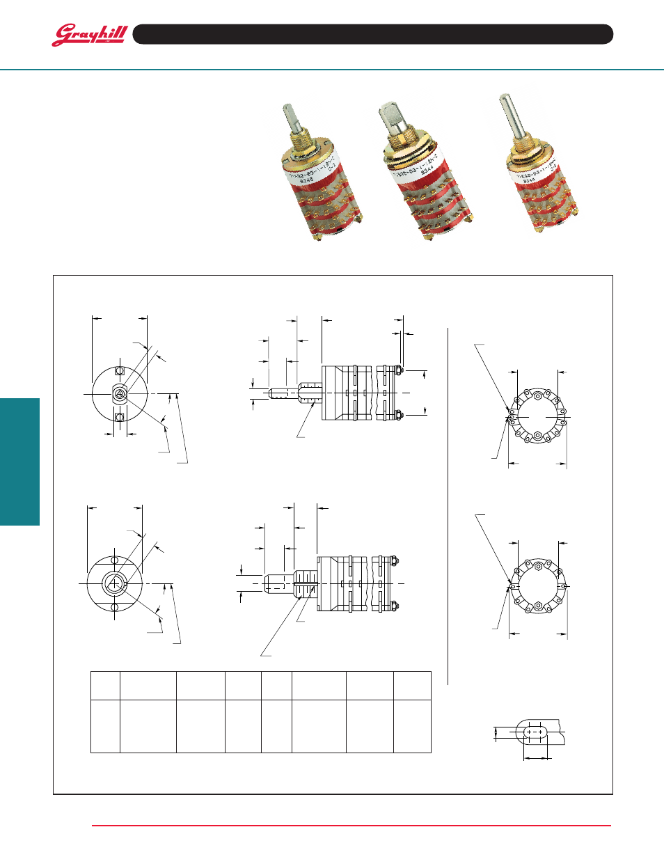
Multi-deck rotary switches series 71, Dimensions: standard and military, Terminal detail
Grayhill, Inc. • 561 Hillgrove Avenue • LaGrange, Illinois 60525-5997 • USA • Phone: 708-354-1040 • Fax: 708-354-2820 • www.grayhill.com
Rotary Switches
Multi-Deck Rotary Switches
SERIES 71
.5-.75" Diameter, 1/4 Amp
FEAtuRES
• Performance and Value Leader
• Molded-In Position Terminals
• Choice of Shaft/Bushing Diameters
• 30° and 36° Angles of Throw
• Military Qualified MIL-DTL-3786/39
0.125" Diameter Shaft–Styles A and MA (and sealed versions)
Rear Views–Style A, B, MA, MB
(and sealed versions)
36° Angle of throw
terminal Detail
Note: Common location for a single pole per
deck switch. For common location on
multipole switches see circuit diagrams.
DIMENSIONS: Standard and Military
in inches (and millimeters)
30° and 36° Angle of Throw may be
interposed on either shaft diameter.
30° Angle of throw
All dimensions not shown
are the same as above.
0.250" Diameter Shaft–Styles B and MB (and sealed versions)
Approx.
Approx.
No. of
Dimension
Dimension
Weight
No. of
Dimension
Dimension
Weight
Decks
A
B
Grams
Decks
A
B
Grams
1
.761 (19,33)
.031 (0,79)
14
7
2.349 (59,66)
.312 (7,92)
26
2
.979 (24,87)
.031 (0,79)
16
8
2.567 (65,20)
.312 (7,92)
28
3
1.197 (30,40)
.031 (0,79)
18
9
2.785 (70,74)
.312 (7,92)
30
4
1.415 (35,94)
.031 (0,79)
20
10
3.003 (76,28)
.312 (7,92)
32
5
1.633 (41,48)
.031 (0,79)
22
11
3.221 (81,81)
.312 (7,92)
34
6
2.131 (54,13)
.312 (7,92)
24
12
3.439 (87,35)
.312 (7,92)
36
Angle C is 15° in 12 position switches and 36 ° in 10 position switches.
Grayhill part number and date code marked on detent cover label. Customer part
number marked on request. Military part number marked when required.
1/4 32UNEF-2A THREAD
.125 + .001
–.002 DIA.
(3,18 + 0,25
–0,05)
.312 ± .020
(7,92 ± 0,51)
.250 ± .020
(6,35 ± 0,51)
.375 ± .020
(9,53 ± 0,51)
.562
± .015
(14,27
± 0,38)
DIM. A ± .046 (1,17)
DIM. B REF.
STUD PROJECTION
(SEE CHARACTER-
ISTICS)
.687 ± .015
(17,45 ± 0,38)
DIA.
.094 ± .010
(2,39 ± 0,25)
.203 ± .005
(5,16 ± 0,13)
OF POSITION NO. 1
OF BUSHING FLATS
C
SEE
CHART
C
L
C
L
GRAyHILL
12
1
3
4
6
7
8
9
10
11
.500 ± .015
(12,7 ± 0,38)
DIA.
.750 ± .020
(19,05 ± 0,51)
OVER TERMINALS
SEE DETAIL
SEE NOTE
2
5
.312 ± .020
(7,92 ± 0,51)
.250 + .001
–.002 DIA.
(6,36 + 0,25
–0,05)
.250 ± .020
(6,35 ± 0,51)
.375 ± .020
(9,53 ± 0,51)
BUSHING KEyWAy
.066 ± .002 (1,68 ± 0,05) WIDE By
.036 ± .003 (0,91 ± 0,08) DEEP
FROM A .375 (9,53) DIA.
3/8-32UNEF-2A THREAD
.687 ± .015
(17,45 ± 0,38)
DIA.
C
SEE
CHART
C
L OF POSITION NO. 1
C
L OF BUSHING KEyWAy
.219 ± .004
(5,56 ± 0,10)
GRAyHILL
10
1
2
3
4
5
6
7
8
9
.500 ± .015
(12,7 ± 0,38)
DIA.
.750 ± .020
(19,05 ± 0,51)
OVER TERMINALS
SEE DETAIL
SEE NOTE
.034 ± .003
(0,86 ± 0,08)
.068 ± .005
(1,73 ± 0,13)