Multi-deck rotary switches, Specifications: electrical ratings, others, Electrical ratings general – Grayhill Multi-Deck Rotary Switches 71 Series User Manual
Page 10: Electrical ratings standard style, Electrical ratings military style
Grayhill, Inc. • 561 Hillgrove Avenue • LaGrange, Illinois 60525-5997 • USA • Phone: 708-354-1040 • Fax: 708-354-2820 • www.grayhill.com
Rotary Switches
Multi-Deck Rotary Switches
SPECIFICAtIONS: Electrical Ratings, Others
Standard
Military
Electrical Ratings
General
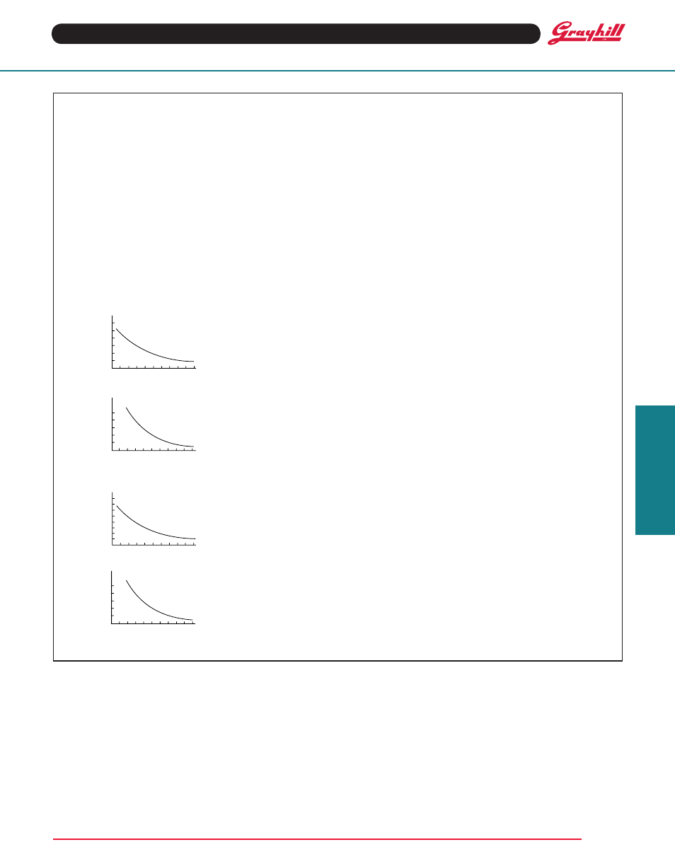
Charts: Charts shown are for non-shorting
(break before make) contacts. Measurements
were made at 25°C and 68% relative humidity.
The load life curves show the number of
rotational cycles which can be expected for the
voltage, current and type of load. Thus, for a
standard style switch with a 300 milliampere 115
Vac resistive load, the expected life is 15,000
cycles. Reducing the load to 200 milliamperes
increases the life to 25,000 cycles. Life limiting
or failure criteria are listed in the rating sections
which follow.
Cycles: A cycle is a 360° rotation and a return
through all switch positions to the starting
position.
Voltage: As listed in charts.
CyCLES x 1000
CURRENT MILLIAMPS
CyCLES x 1000
CyCLES x 1000
CyCLES x 1000
CURRENT MILLIAMPS
CURRENT MILLIAMPS
CURRENT MILLIAMPS
VOLTAGE 115 VAC
OR 30 VDC
RESISTIVE
250
200
150
100
50
10
25
50
10
25
50
400
300
200
100
500
600
VOLTAGE 30 VDC
INDUCTIVE
(250 MILLIHENRIES)
VOLTAGE 115 VAC
OR 30 VDC
RESISTIVE
VOLTAGE 30 VDC
INDUCTIVE
(250 MILLIHENRIES)
10
25
50
400
300
200
100
500
600
10
25
50
200
150
100
50
250
800
700
MILItARy
StANDARD
CyCLES x 1000
CURRENT MILLIAMPS
CyCLES x 1000
CyCLES x 1000
CyCLES x 1000
CURRENT MILLIAMPS
CURRENT MILLIAMPS
CURRENT MILLIAMPS
VOLTAGE 115 VAC
OR 30 VDC
RESISTIVE
250
200
150
100
50
10
25
50
10
25
50
400
300
200
100
500
600
VOLTAGE 30 VDC
INDUCTIVE
(250 MILLIHENRIES)
VOLTAGE 115 VAC
OR 30 VDC
RESISTIVE
VOLTAGE 30 VDC
INDUCTIVE
(250 MILLIHENRIES)
10
25
50
400
300
200
100
500
600
10
25
50
200
150
100
50
250
800
700
MILItARy
StANDARD
Electrical Ratings
Standard Style
Curves are based on the following failure
criteria:
Contact Resistance: 50 milliohms maximum
(20 milliohms initially).
Insulation Resistance: 1,000 megohms
minimum between terminals and shaft. (50,000
megohms initially).
Voltage Breakdown: 500 Vac minimum between
mutually insulated parts.
Current Rating: These switches will carry 4
amperes with a maximum contact temperature
rise of 20°C. If the life limiting characteristics
are less critical than those shown above, if
elevated temperatures or reduced pressures
are involved, Grayhill can predict the switch life
for the application.
Meet the Following Requirements of MIL-
DtL-3786: Moisture Resistance: Medium and
High Shock; Vibration (10 to 2,000 cps); Thermal
Shock (-65°C to 85°C); Salt Spray, Explosion;
and Stop Strength (10 in-lb).
Electrical Ratings
Military Style
Curves are based on the following failure
criteria:
Qualified to the following MIL-DtL-3786/39
circuit values: (also see standard style
description.) The Series 71 has been tested to
meet the requirements of MIL-DTL-3786, Style
SR39, the majority of which are listed here. At
85°C approximately 68% relative humidity and
sea level pressure, the switches have been
tested to make and break the following loads,
as stated in MIL-DTL-3786/39: 125 milliamperes
at 28 Vdc resistive; 75 milliamperes at 115 Vac
resistive.
The switches have also been tested at reduced
barometric pressure (70,000 feet), 25°C at
approximately 68% relative humidity to make and
break the following loads as stated in MIL-DTL-
3786/39: 50 milliamperes, 28 Vdc resistive; 20
milliamperes, 115 Vac resistive. When tested to
the above loads at stated conditions, the Series
71 switches meet the following life-limiting criteria
after 25,000 cycles of operation in accordance
with MIL-DTL-3786/39.
Contact Resistance: 50 milliohms maximum
after life.
Insulation Resistance: 1,000 megohms
minimum between terminals and shaft.
Dielectric Strength: 500 Vac (atmospheric
pressure) and 350 Vac (reduced pressure)
between mutually insulated parts.
The Series 71 also meets the requirements
of MIL-DTL-3786/39 for moisture resistance,
stop strength, rotational torque, vibration (10
through 2,000 cps), medium and high shock,
salt spray, explosion, thermal shock (-65°C
to 85°C) and terminal pull. When tested at
sea level, 25°C and 68% relative humidity
with failure criteria of 50 milliohms maximum
contact resistance and 500 Vac breakdown
voltage, these switches will make and break 250
milliamps at 28 Vdc inductive (250 millihenries)
500 milliamps at 28 Vdc resistive: 500 milliamps
at 115 volts Vac, 60 hertz resistive, for 10,000
cycles of operation.
Additional Characteristics
Standard and Military Styles
Rotational torque: 4-32 ounce-inches, (28-
230 N•mm) depending on the number of poles
per deck and the number of decks.
Contacts: Shorting or non-shorting wiping
contacts with over 100 grams of contact
force.
Shaft Flat Orientation: Opposite first position
pole no. 1 (See Circuit Diagrams).
terminals: Switches are provided with full
circle of terminals regardless of the number
of active positions.
Extended Studs: Switches of 6 or more
decks (or concentric switches of 4 or more)
have longer studs and extra stud nuts for
recommended double end mounting. Stud hole
size is
1
/
16
" diameter for #0-80 NF-2A thread.
Stop Strength: 10 pound-inches.
Mounting Bushing Strength: 10 pound-
inches.