Grayhill Special Function Rotary Switches 50 Series User Manual
Special function rotary switches, Dimensions selecting a switch, Description
Grayhill, Inc. • 561 Hillgrove Avenue • LaGrange, Illinois 60525-5997 • USA • Phone: 708-354-1040 • Fax: 708-354-2820 • www.grayhill.com
Rotary Switches
Special Function Rotary Switches
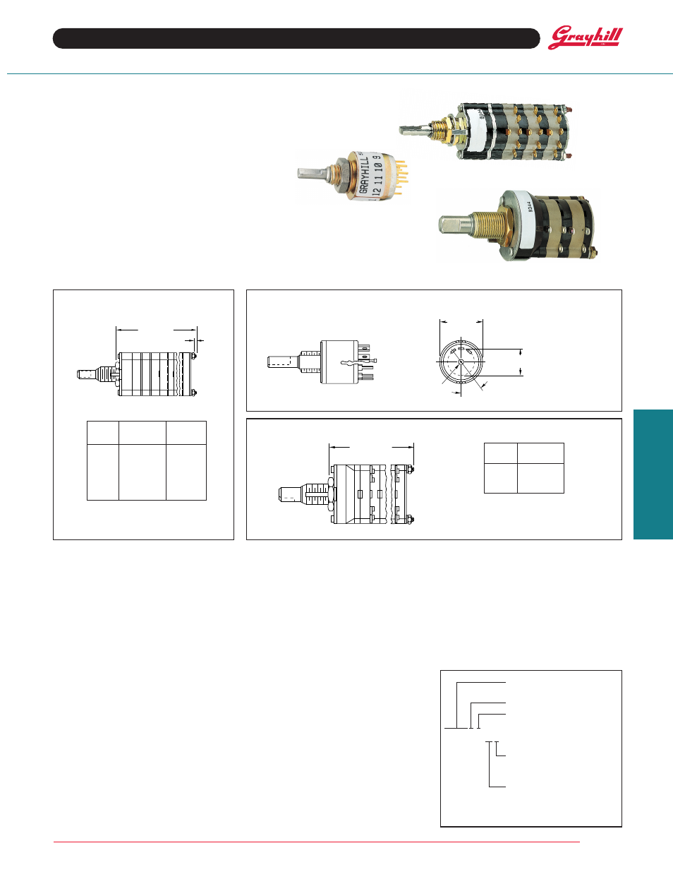
DIMENSIONS
SELECTING A SWITCH
1. Select a Configuration: The total number of
positions always includes the 2 basic positions.
A (4) position switch of DDD
DM configuration
would have 3 detent positions counterclockwise
of the momentary position.
2. Select Series, Angle of Throw, and Style:
See the Choices Chart. The basic switch
description, series, and throw are as follows:
1
/
2
",
1
/
4
Amp, multi-deck
08 = 36° 09 = 30°
1", 1 Amp, multi-deck
42 = 36° 44 = 30°
1
/
2
", 200 mA, single deck
50 = 36°
Electrical ratings are the same as those of the
conventional switches with the exception of life.
Life is limited to 10,000 cycles of operation
(25,000 cycles for Series 50) due to the spring
arrangement. Dimensions are the same as for
conventional types except for the shaft flat
orientation of the 3, 4, 5, and 6 pole, Series 09
and 44 in the DDDD
DM configuration (see
chart).
3. Select Poles & Positions Per Pole: If you
do not find the poles and positions per pole you
need in one series, try another or contact the
factory. If the behind panel length is a problem,
select a multi-pole type instead of a single deck.
FEATURES
• Hold-To-Test, Hold-To-Calibrate,
And Other Momentary Applications
• Choice of Configurations, Ratings,
Styles and Circuitry
• 10,000 Cycles of Operation
Series 42 & 44
Series 50
Equivalent to Series 50 Standard Switches
Series 08 & 09
For all other dimensions and
specifications, see Standard
Switch pages.
No. of
Dim
Dim
Decks
A
B
1
.960 (24,38)
.062 (1,57)
2
1.228 (31,19)
.062 (1,57)
3
1.496 (38,0)
.062 (1,57)
4
1.764 (44,81)
.062 (1,57)
5
2.032 (51,61)
.062 (1,57)
6
2.550 (64,77)
.312 (7,92)
For all other dimensions and
specifications, see Standard
Switch pages.
No. of
Dim.
Decks
A
1
1.025 (26,04)
2
1.371 (34,82)
3
1.717 (43,61)
DESCRIPTION
A spring return rotary switch has 1 or more momentary positions. Maintaining contact at momentary
positions requires rotational force. Releasing the force allows the mechanism to return the contact
to a normal, or detent, position.
CONFIGURATIONS
This configuration indicates a counterclockwise
force is required to hold the switch at position
#1. “M” indicates a momentary position
counterclockwise of “D” and "D", detented ones.
Positions
1
2
3
M
D
D
Releasing this force breaks contact with position
#1 and returns the switch to #2. Normal rotary
switch detent action occurs when the switch is
rotated between position #2 and #3.
All of the configurations (except
MDM) list a
basic 2 position arrangement which is shown in
italics. Example:
MDDDDD or DDDDDM. Several
positions can be added during the switch
construction at the factory; but, any configuration
must always contain the 2 basic positions.
OPTIONS
Watertight panel seal; Multi-pole switches that
exceed the limits noted in the Selector Chart;
Series 50
MD or DM configurations in Military
styles; Series 08, 09, & 44 in MM
MDMMM, and
in MM
DDMM, and in MMMMMD.
Not available through Distributors
ORDERING INFORMATION
Create the part number using this example.
Exception: Numbers beginning with 5 are
already complete part numbers.
Stem number from chart
(4 or 5 digits)
Number of Decks
Number of Poles/Deck
093103-2-045
Type of Contacts:
S=Shorting
N=Non-Shorting
Number of Positions/Pole
For all other dimensions and
specifications, see Standard
Switch pages.
SERIES 08,09,42,44,50
Spring Return
DIM. A + .046 (1,17)
–.020 (0,51)
DIM. B REF.
STUD PROJECTION
.500 ± .015
(12,7 ± 0,38)
DIA.
.320 ± .015 (8,13 ± 0,38)
CIRCLE OF CENTERS
COMMON
36°
± 3°
DIM. A + .046 (1,17)
–.020 (0,51)