Multi-deck rotary switches – Grayhill Multi-Deck Rotary Switches 54 Series User Manual
Page 9
Grayhill, Inc. • 561 Hillgrove Avenue • LaGrange, Illinois 60525-5997 • USA • Phone: 708-354-1040 • Fax: 708-354-2820 • www.grayhill.com
Rotary Switches
Multi-Deck Rotary Switches
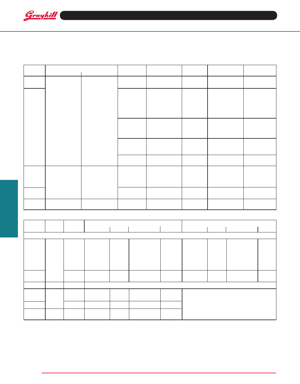
CHOICES AND LIMItAtIONS: Series 42, 43, 44 and 54
A = Standard, Solder Lugs
P = Standard, PC Mount Terminals
D = Standard, Adjustable Stops
S = Shaft and Panel Seal
U = UL Recognized
M = Military Qualified 85°C
4
H = Military Qualified, 125°C
B = Military, Grounded Shaft
G = Military, Low Level Rating
SINGLE SHAFt SWItCHES
Style Choices
Angle of
Number of
Poles
Positions
Shorting or
Series
unsealed
Shaft/Panel Seal
throw
Decks
Per Deck
Per Pole
1,3
Non-Shorting
01 thru 12
1
02 thru 10
3
N or S
01 thru 12
2
02 thru 05
N or S
01 thru 12
1
02 thru 12
3
N or S
01 thru 12
2
02 thru 06
N or S
01 thru 08
3
02 thru 04
N or S
01 thru 06
4
02 or 03
N or S
01 thru 04
5
02
N or S
01 thru 04
6
02
N or S
01 thru 12
1
02 thru 08
3
N or S
01 thru 06
2
02 thru 04
N or S
01 thru 04
3
02
N
01 thru 03
4
02
N
01 thru 12
1
02 thru 06
3
N
01 thru 06
2
02 or 03
N
01 thru 04
3
02
N
01 thru 12
1
02 thru 04
3
N
01 thru 06
2
02
N
01 thru 12
1
AJ (2 thru 12)
1
N or S
01 thru 12
2
AJ (2 thru 6)
1
N or S
01 thru 08
3
AJ (2 thru 4)
1
N or S
01 thru 06
4
AJ (2 or 3)
1
N or S
01 thru 12
1
AJ (2 thru 10)
1
N or S
01 thru 12
2
AJ (2 thru 5)
1
N or S
01 thru 12
1
02 thru 10
3
N or S
A
S
UA
US
UM
5
—
M
MS
4
MB
MBS
4
MG
MGS
4
MBG
MBGS
4
H
HS
HB
HBS
HG
HGS
HBG
HBGS
D
—
UD
—
P
SP
UP
USP
1
For Adjustable Stop (with the letter D), use AJ
instead of number of positions when ordering.
2
For 45°, 60° or 90° throws in Series 54 switches
of these styles, see Standard Options.
3
For single pole switches with the maximum
positions per pole, continuous rotation is possible.
Specify fixed stop or continuous rotation when
ordering single shaft switches. Concentric shaft
switches have continuous rotation.
Style
Angle of
Section A (Front)
Section B (Rear)
Series
Choices throw
Decks
Poles
Position
N or S
Decks
Poles
Position
N or S
CONCENtRIC SHAFt, 2 SWItCHES
A
2
UA
2
M
2
D
UD
M
54
43
54
43
54
ADD-A-POt SWItCHES
Second shaft operates a potentiometer
supplied by the customer.
Rear mounting plates are provided.
30°
36°
30°
36°
30°
01 thru 03
1
02 thru 10
5
N or S
Concentric Shaft Switches
36°
30°
45°
60°
90°
30°
36°
36°
42
44
44
42
42
01 thru 03
1
02 thru 12
3
N or S
01 thru 03
2
02 thru 06
N or S
01 thru 03
1
02 thru 12
3
N or S
01 or 02
3
02 thru 04
N or S
01 thru 03
2
02 thru 06
N or S
01
4
02 or 03
N or S
01
5
02
N or S
01
6
02
N or S
01 thru 03
1
02 thru 10
3
N or S
01 thru 03
2
02 thru 05
N or S
01 thru 03
1
AJ (2-12)
1
N or S
01 thru 03
2
AJ (2-6)
1
N or S
01 thru 03
1
AJ (2-10)
1
N or S
01 thru 03
1
02 thru 12
5
N or S
01 thru 03
2
02 thru 06
N or S
4
Styles which include both M and S are not
qualified but are made of the same materials
and construction as qualified types. For qualified
switches with shaft and panel seal, use equivalent
HS style.
5
UM switches are made of the same materials and
construction as the M style switches. For military
switch UM is not required; use M style.