Multi-deck rotary switches, Accessories – Grayhill Multi-Deck Rotary Switches 54 Series User Manual
Page 10
Grayhill, Inc. • 561 Hillgrove Avenue • LaGrange, Illinois 60525-5997 • USA • Phone: 708-354-1040 • Fax: 708-354-2820 • www.grayhill.com
Rotary Switches
Multi-Deck Rotary Switches
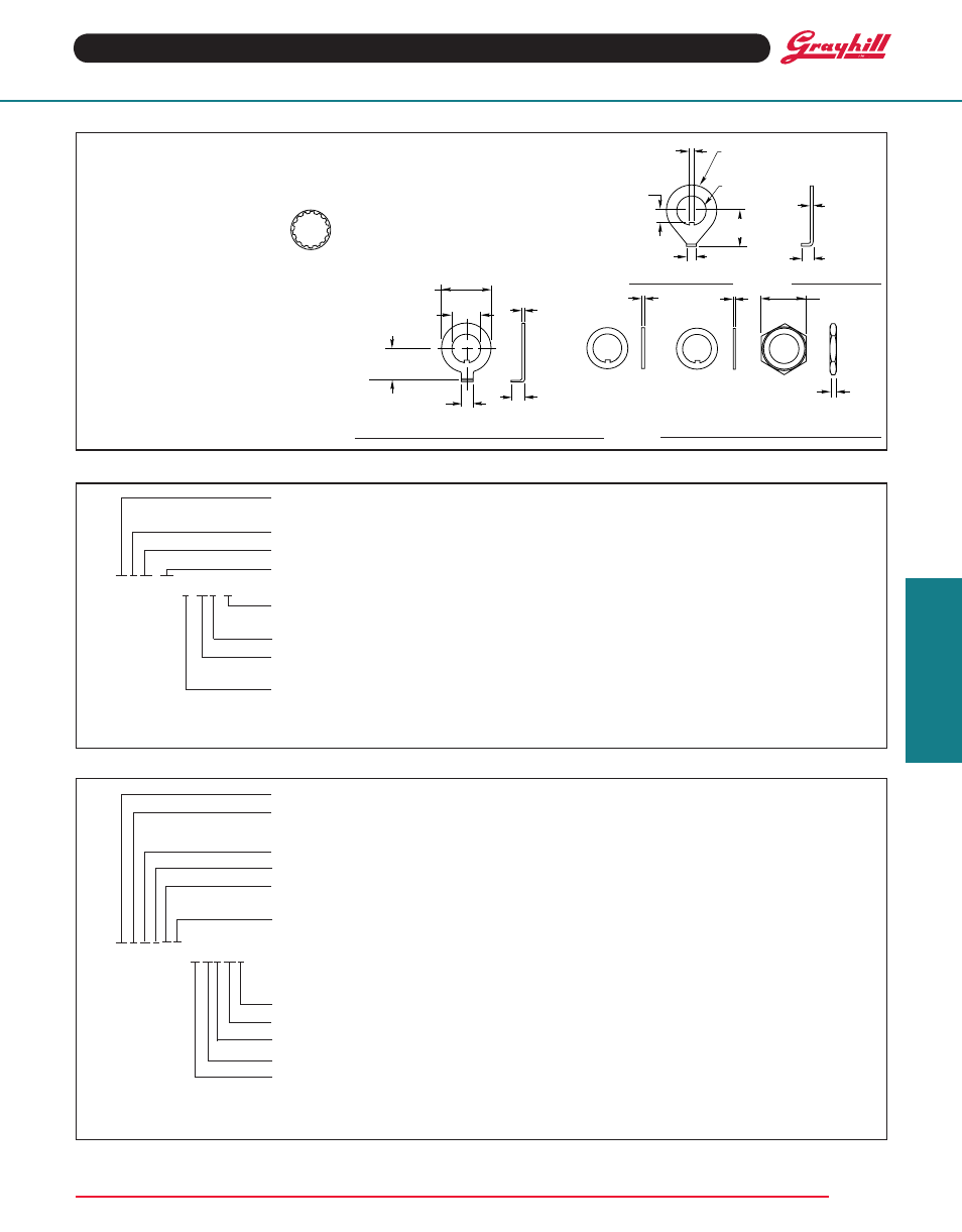
ACCESSORIES
Internal tooth Lockwasher–Figure A
For a
3
/
8
" bushing. Approximately 0.500" (12,7)
outside diameter, .022" (0,56) thickness.
Material is cadmium-plated steel. Part
No.
12Q1272-1
For a
1
/
4
" bushing. Approximately
0.400" (10,16) outside diameter,
.018" (0,46) thickness. Material is
steel, tin/zinc plated.
Non-turn Washer–Figure B
Can be ordered as extra hardware for the Series
5000, 24, 42, 43, 44, 54, 71B, 53, 57 and 59
rotary switches. The internal key of the washer
slides into the bushing keyway. The right angle
tab locks into a predrilled hole on the back side
of the mounting panel. Material is brass, tin/zinc
plated.
Part No. 12C1087-1
Panel Seal Kit–Figure C
Sold as a separate item to seal the switch
ORDERING INFORMAtION: Single Shaft Switches, Add-A-Pot Switches
ORDERING INFORMAtION: Concentric Shaft Rotary Switches
Series: Determined by the type of switch and
the angle of throw
Style*: Letter(s) from the Choices and Limitations chart
Angle of Throw: Must agree with Series Number
Number of Decks: As limited by the angle of throw, the poles per deck, switch style and type of contacts
44M30–02–1–12N–F
Stop Arrangement: Add letter F to a one pole per deck switch with the maximum number of positions for a
stop between position 1 and the last position. Leave blank for continuous rotation
type of Contacts: N = Non-shorting; S = Shorting
Positions Per Pole: Requires 02 positions as a minimum to maximum allowable dependent on the angle of
throw and poles per deck. Use AJ for adjustable stops (Styles D and UD).
Poles Per Deck: As limited by angle of throw, switch series and style
* All rotary switches that are required to have military designated markings and testing adhering to MIL-3786 are to be ordered by specifying
the military part number identified on the appropriate slash sheet.
Series: Determined by the angle of throw, applicable to both sections
Style*: Letter(s) from the Choices and Limitations chart
Section A (front)
Number of Decks: As limited by the number of poles per deck
Poles Per Deck: As limited by the angle of throw
Positions Per Pole: Requires 02 positions as a minimum to the maximum allowable dependent on the
angle of throw and the poles per deck
type of Contacts: N=Non-shorting, S=Shorting. All one pole per deck switches with the maximum number
of positions are continuous rotation
43M02110N–M03203S
Section B (rear)
The limitations listed for Section A apply to Section B
type of Contacts
Positions Per Pole
Poles Per Deck
Number of Decks
Style
* All rotary switches that are required to have military designated markings and testing adhering to MIL-3786 are to be ordered by specify-
ing the military part number identified on the appropriate slash sheet.
Available from your local Grayhill Distributor
For prices and discounts, contact a local Sales Office, an authorized local Distributor or Grayhill.
Non-turn Washer Seal Keyed Washer Hex Nut
FIGuRE C
.625 ± .010
(15,88 ± 0,25) DIA.
.375 + .004 – .000
(9,53 + 0,10) DIA.
.375 ± .005
(9,53 ± 0,13)
.125 ± .003
(3,18 ± 0,08)
C
L
.032
± .002
(0,81
± 0,05)
.187 ± .010
(4,75 ± 0,25)
.045 ± .003
(1,14 ± 0,08)
.010 ± .002
(0,25 ± 0,05)
.562 (14,27)
ACROSS
FLATS
.088 (2,24)/
.093 (2,36)
.120 ± .003
(3,18 ± 0,08)
.060 ± .002
(1,52 ± 0,05)
.154
+ .004
–.000
(3,91
+ 0,10
–0,00)
DIA.
.437 ± .010
(11,10 ± 0,25)
.625 ± .010
(15,88 ± 0,25)
DIA.
.376 + .003 –.000
(9,55 + 0,08 –0,00)
DIA.
.125 ± .010
(3,18 ± 0,25)
.032 ± .002
(0,81 ± 0,05)
FIGuRE B
FIGuRE A
bushing to the panel. The kit consists of four
items: a grooved hex nut, a keyed washer, a
keyed seal and a non-turn washer. Assembly is
described on Page J-53. Dimensions of panel seal
kit items are shown in Figure C. This kit seals the
bushing to the panel; it does not seal the shaft
to the bushing. Not usable with adjustable stop
switches.
Part No. 42-24