Alignment of the px3000e100tp – GeoDesy GD-3000 Series User Manual
Page 20
20
7.1.1 Alignment of the PX3000E100TP
The first step after the unit was placed to the
bracket, and the units facing each other.
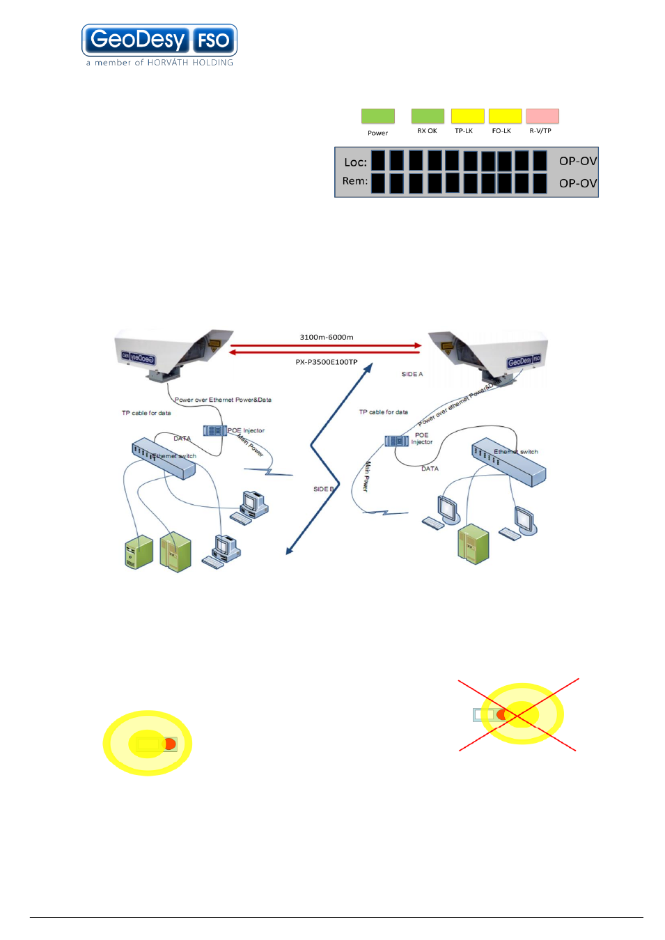
On the back of the receiver you can find
the LEDs and LCD screen for the local
received level and the remote received
level. This help will be very useful
because as soon as you have received
– which is very easy to achieve – you can
see the effect of your local sides movement to the other side. For further information
please check the Meanings of the LEDs chapter.
System layout
Note: Geodesy FSO shall not be responsible for any failures from improper handling
of the device. If any other screw than the coarse lockers or the fine adjustment is
moved, might decrease the stability of the installation.
Trick for the reliable alignment
Please note that the beam has a powerfull ring on the side of the head and easily can be
set to this ring but this is far not as big as the core
part of the beam. So every time you have an
alignment please make sure that when you see the
maximum LED s or a relativly high received level.
Keep on moving to determine where the core part of
the beam is. This can be done easily by looking at
the received level you will see that the received level moves up then it will start move
down than up again. During this time you just had the head moving into one direction. If
you have any doubt on how to do the alignment please contact your distributor for further
help. Or contact GeoDesy FSO technical support.