Beam alignment, 2 beam alignment – GeoDesy GD-3000 Series User Manual
Page 17
17
6.2 Beam Alignment
Swich off all of the transmitters on both sides.
Switch on one of your transmitters on one side.
Move the beam the middle of the remote head.
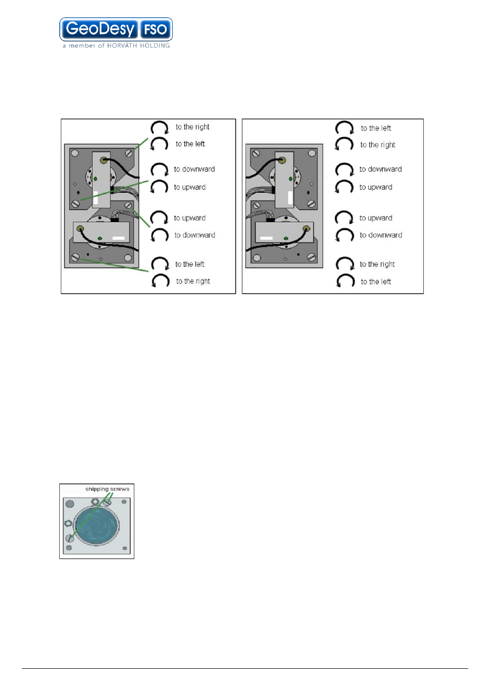
You can move the beam with the screws on the back of the transmitters. The
directions of beam moving in the functionof the turning direction of the screws can
be seen on the figure.
You can check the position of the beam using a digital camera with infared lenses.
You can see the beam shining on the landmarks around the remote head from the
side of the transmitter, or until dusk you can see the line of the beam with your own
eyes.
From the remote side you can see the light of the beam behind the head with the
shadow of the head on a surface (for example on a wall), or if you see toward the
side of the transmitter, there you can see shining the beam on landmarks, and with
the growing and declining of the shining rounded plate, which is the beam, you can
follow its moving.
Repeat the beam alignment with each transmitters on both sides.
In every transmitter there are twoshipping screws against the
bigger moving of the tube. These screws allow only less movings
for the transmitters, so if you need bigger moving you have to
pick them out first.
Anyway, GeoDesy-FSO strongly recomends that you take all of
them out first…