Inside the laserhead, Alignment, Lcd panel (receiver) aligment – GeoDesy GD-3000 Series User Manual
Page 15: 5 inside the laserhead, 6 alignment, 1 lcd panel (receiver) aligment
15
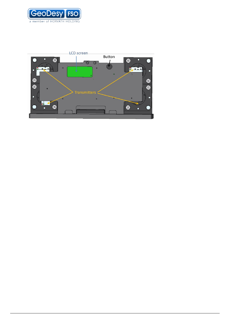
5.5 Inside the laserhead
Warning
only trained personal should open the casing. No user servicable part
inside.
6 Alignment
The very first step is to power up the heads. After this the boot sequence should run
down, which takes 10-15 seconds.
6.1 LCD panel (receiver) Aligment
Important!
For alignment purposes you might need a computer connected to the
system. The adjustment of the motor control, and the swithcing of the transmitters
are possible with a PC.
For adjustment please see PX-3000E100TP extra MGM functions chapter.(30 page)
For manual disabling please follow the below:
Turning off the motor control: Restart the laser head during boot and pull out
the plug while booting. After plugging in the motor controler will turn off.
The motor control is a “light-buffer” this saves the power for the bad weather and in
the same time protects the receiver against overload.
During the alignment it can be used manually, to avoid the saturation, and keep the
detector voltage on the level where it can be still monitored. The detector voltage
can be increased to seven volts; above seven volts you won’t be able to monitor the
detector voltage.
This plate is located in front of the receiver, and you can rotate it (clockwise
decreases the detector voltage, counter- clockwise increases).