Flint & Walling Centrifugal Packages - end suction centrifugal pumps User Manual
Page 4
4
95 North Oak Street • Kendallville, IN 46755
Copyright 2011. All Rights Reserved.
SINGLE PHASE
Distance From Motor
To Fuse Box Meter,
or Electrical Outlet
Recommended Copper Wire Size
1HP
1-1/2 HP
2 HP
3 HP
5 HP
100 ft.
115V
230V
10
14
8
12
8
10
*
8
-
6
150 ft.
115V
230V
6
12
6
12
4
10
*
8
4
200 ft.
115V
230V
6
12
6
10
4
8
*
6
-
4
300 ft.
115V
230V
*
12
*
6
*
6
*
4
-
2
500 ft.
115V
230V
*
10
*
4
*
4
*
2
-
0
(*) Not economical to run at 115V, use 230V.
Figure 3
THREE PHASE
Distance From
Motor To Fuse
Box Meter, or
Electrical Outlet
Recommended Copper Wire Size
1HP
1-1/2
HP
2 HP 3 HP 5 HP
7-1/2
HP
100 ft.
230V
460V
14
14
12
12
12
12
12
12
10
12
8
12
150 ft.
230V
460V
14
14
12
12
12
12
10
12
8
12
6
12
200 ft.
230V
460V
14
14
12
12
12
12
10
12
8
12
6
12
300 ft.
230V
460V
12
14
12
12
10
12
8
12
6
10
4
10
500 ft.
230V
460V
10
14
10
12
8
12
6
10
4
8
2
8
Figure 4
MOTOR PROTECTION
WARNING: Never examine, make wiring changes
or touch the motor before disconnecting the main
electrical supply switch.
1.
Motors may or may not have built-in thermal
overload protection depending upon the
horsepower size, phase, type and motor
manufacturer. Refer to the motor nameplate for
overload protection information. It is recommended
that a properly sized magnetic or manual starter
(both with properly sized heaters) be used with all
motors. Install starters following instructions of the
starter manufacturer. See Figure 5 & 6 for magnetic
starter wiring diagram.
2. All motors (single and three phase) should be
equipped with a correctly fused disconnect switch
to provide protection. Consult Local or National
Electrical Codes for proper fuse protection based on
motor nameplate.
3. Undersize wiring can cause motor failure (low
voltage), frequent cut-out of motor overload
protector, television interference and even fire.
Make certain the wiring is adequately sized (Figure
3 & 4), well insulated and connected to a separate
circuit outside the building in case of fire.
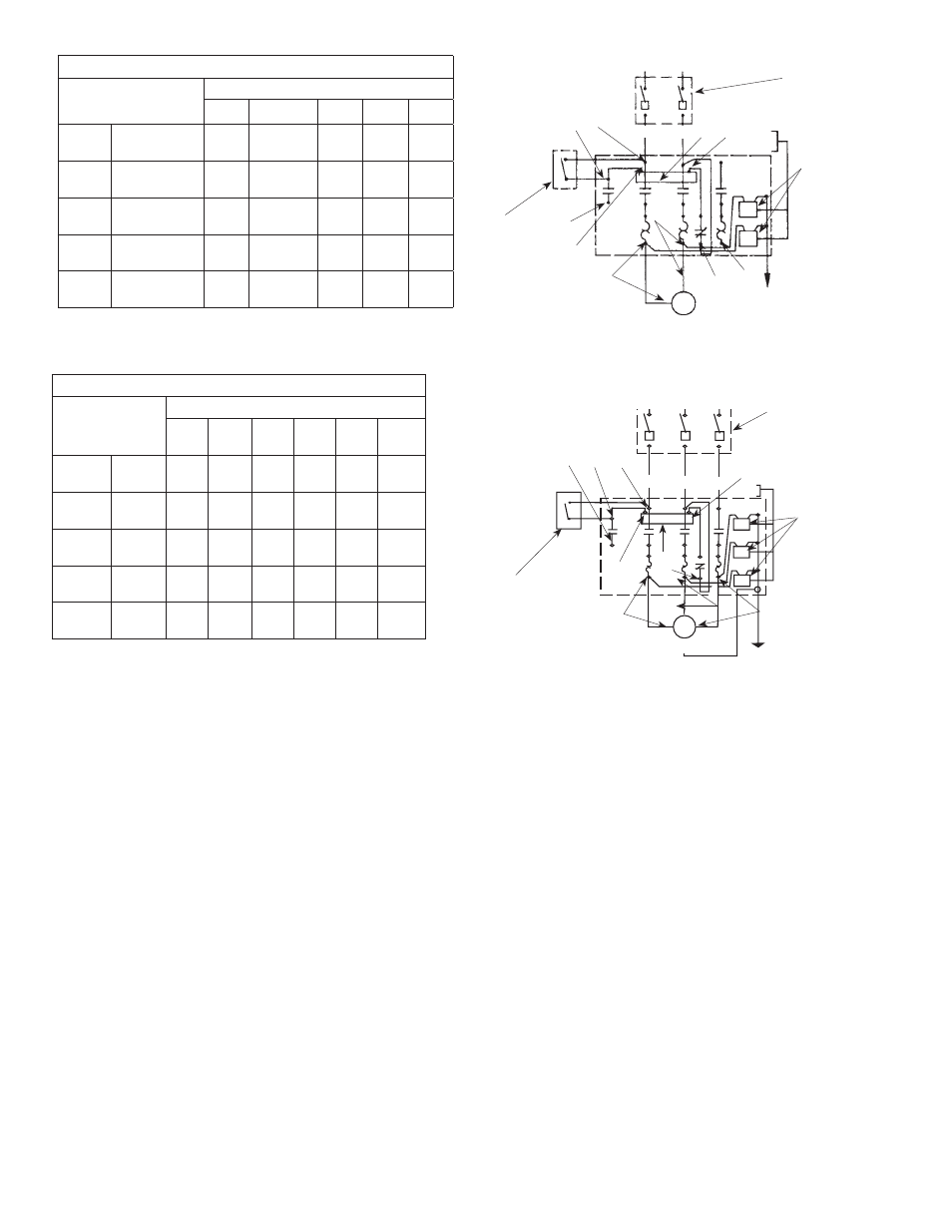
Figure 5
Warning: Connect
motor leads
momentarily for
correct rotation
Motor
Pressure
Switch
Magnetic Starter Wiring
Diagram - Single Phase
Fused
Disconnect
Switch
Lightning
Arrestors
#10 Or Heavier Copper Ground Wire,
Connect To 8 ft. Ground Rod Or Well Casing
L1
L2
3
2
1
V
M
W
T1
T2
T3
X2
IL0102
Figure 6
Pressure Switch
Magnetic Starter Wiring
Diagram - Three Phase
Fused Disconnect
Switch
Lightning
Arrestors
#10 Or Heavier Copper Ground Wire,
Connect To 8 ft. Ground Rod Or Well Casing
Motor
1
W
V
T3
X2
T2
T2
T1
M
L3
L2
L1
3
2
OPERATION
PRIOR TO STARTING
1. Before the pump is started initially, make the
following inspections:
• Check Rotation - Be sure that the pump operates in
the direction indicated by the arrow on the pump
casing, as serious damage can result if the pump
is operated with incorrect rotation. Rotation is
always counterclockwise facing the pump suction.
Operating the pump in reverse rotation may cause
extensive damage.
• Check all connections to motor and starting device
with wiring diagram. Check voltage, phase and
frequency on motor nameplate with line circuit.
ALL PUMPS WITH 3 PHASE MOTORS MUST BE
INSTALLED WITH A MAGNETIC STARTER WHICH
PROVIDES 3-LEG PROTECTION FOR MOTOR.
FAILURE TO USE CORRECT STARTER WILL VOID THE
WARRANTY.
PRIMING
1. Before starting any centrifugal pump it is absolutely
necessary that both the casing and suction pipe be