Flint & Walling Centrifugal Packages - end suction centrifugal pumps User Manual
Page 3
3
95 North Oak Street • Kendallville, IN 46755
Copyright 2011. All Rights Reserved.
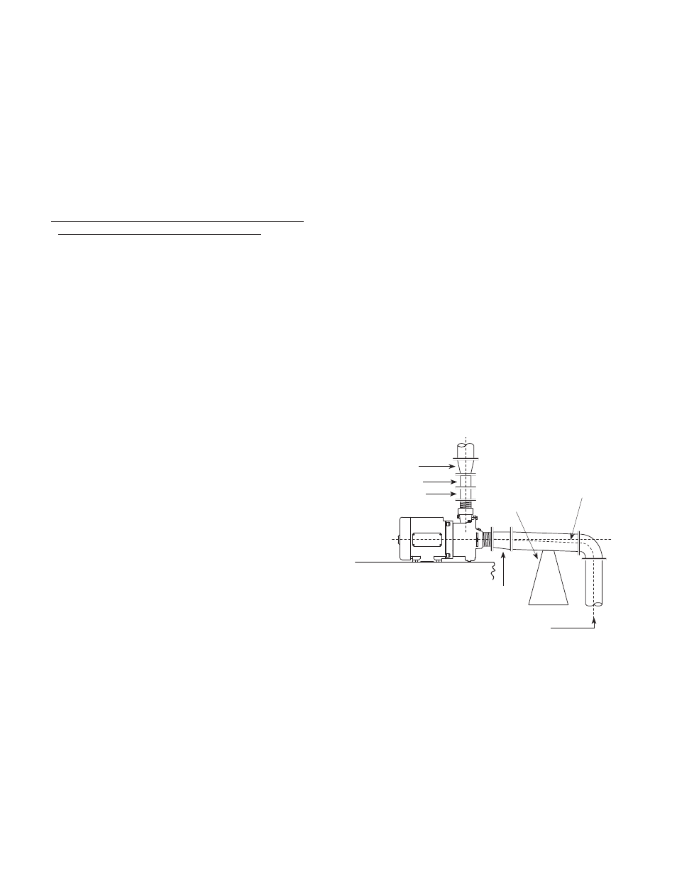
reducer with the eccentric side down to avoid air
pockets. Never use a straight taper reducer in a
horizontal suction line, as it tends to form an air
pocket in the top of the reducer and the pipe.
Valves in Suction Piping
1. If the pump is operating under static suction lift
conditions, a foot valve may be installed in the
suction line to avoid the necessity of priming each
time the pump is started.
2. When foot valves are used, or where there are other
possibilities of “liquid hammer”, close the discharge
valve before shutting down the pump.
3. The pump must never be throttled by the use of
a valve on the suction side of the pump. Valves
should be used only to isolate the pump for
maintenance purposes, and should always be
installed in positions to avoid air pockets.
DISCHARGE PIPING
1. On long horizontal runs it is desirable to maintain as
even a grade as possible. Avoid high spots, such as
loops, which will collect air and throttle the system
or lead to erratic pumping.
Valves In Discharge Piping
1. A check valve and gate valve should be installed
in the discharge. The check valve, placed between
the pump and the gate valve, protects the pump
from excessive pressure, and prevents liquid from
running back through the pump in case of power
failure. The gate valve is used in priming and
starting, and when shutting the pump down.
Pressure Gauges
1. Properly sized pressure gauges can be installed
in both the suction and discharge openings in the
gauge taps which are provided. The gauges will
enable the operator to easily observe the operation
of the pump, and also determine if the pump is
operating in conformance with the performance
curve. If cavitation, vapor binding or other unstable
operation should occur, widely fluctuating discharge
pressure will be noted.
ELECTRICAL CONNECTIONS
GROUNDING
1. To reduce the risk of electric shock. The motor must
be securely and adequately grounded to a grounded
metal raceway system or by using a separate
grounding wire connected to bare metal on the
motor frame, or to the grounding screw located
inside motor terminal box, or other suitable means.
Refer to National Electric Code (NEC Article 250
[Grounding]) for additional information.
2. All wiring should be preformed by a qualified
electrician and in accordance with the National
Electric Code, Local Electric Codes and the
Occupational Safety and Health Act (OSHA).
WARNING: Failure to connect the motor frame to
equipment grounding conductor by using green screw
may result in serious electrical shock.
WIRING CONNECTIONS
1. This unit is not water proof and is not intended to
be used in showers, saunas, or other potentially
wet locations. The motor is designed to be used
in a clean dry location with access to an adequate
supply of cooling air. Ambient temperature around
the motor should not exceed 104°F (40°C). For
outdoor installations motor must be protected by a
cover that does not block airflow to and around the
motor. This unit is not weatherproof nor is it able to
be submersed in water, or any other liquid.
2. Motor voltages will vary depending upon the motor
horsepower, phase and manufacturer. Refer to the
motor nameplate for voltage and electrical data.
WARNING: Make certain that the power supply
conforms to the electrical specifications of the motor
supplies. Failure to do so may cause premature motor
failure and will void the warranty.
3
.
For proper electrical connections, refer to the
connection diagram located on the nameplate
or inside the terminal box of the motor. Make
sure connections are correct for the voltage being
supplied to the motor.
4. Whenever possible, the pump should be powered
from a separate branch circuit of adequate capacity
to keep voltage drop to a minimum during starting
and running. For longer runs, increase wire size
in accordance with the Wire Selection Guide. (See
Figures 3 & 4)
IL1001
Suction Pipe Installed
With Gradual Rise To
Pump Inlet
Level
Center Line
of Pipe
Pipe
Support
Increaser
Gate Valve
Check Valve
Eccentric
Reducer
Figure 2
NOTE: Wire charts are for reference only. Consult
local and state codes for approved wire sizes.
WARNING: Always disconnect power source before
performing any work on or near the motor or its
power source. Failure to do so could result in
personal injury or fatal electrical shock.